"Lookin' for some hot stuff, baby, this evenin'..." - Donna Summer
It's time to dive feet first into what I've never done before: make a circuit. I figured this would be a good opportunity to make the inductor heating coil.
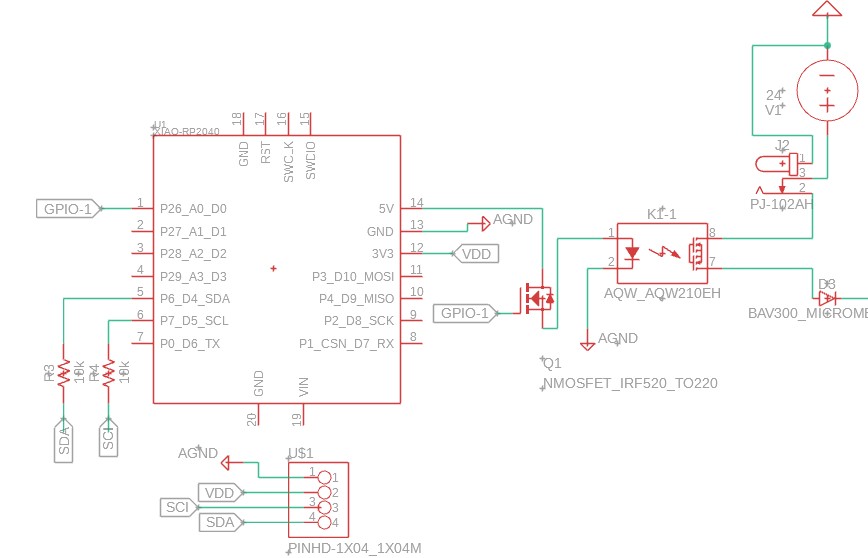
I figured I could control the activation of the inductor with the GPIO pins of the Xiao RP2040 and a MOSFET linked to a solid-state relay: separating the higher-voltage resonance circuit from the microcontroller. Furthermore, to relay system status (without having to put a wrench or piece of metal in the heating coil), I propose using a simple OLED display communicating with the Xiao via I2C - it's well-established in this class, and telemetry isn't the primary focus of this project.
In theory, a heating inductor is relatively simple to make: put a capacitor and inductor in parallel, maximize capacitance and inductance to reduce the current alternation frequency - the lower the frequency, the deeper within the metal a current is induced. Because there are natural losses within an induction resonance circuit, there has to be a way to 'resupply' current lost with each cycle. I figured a mosfet would be a good way to complete the circuit and provide current as the potential changes direction when the capacitor bank charges and recycles. This was as far as my own reasoning could take me, so then I began looking for examples online...

I was incredibly confused and spent a metric ton of time trying to understand how on Earth an inductor worked. Why were there diodes? Why were there inductors beside the main heating coil? To make sense of the chaos, I began experimenting with simulating a "Zero Voltage Switch" resonance circuit patented by Mazili. The simulation of this circuit can be found below:
By experimenting with the available components, I came to a simplified architecture shown below. It has more current losses, but I'm not particularly interested in copying someone else's circuit for this class. I'll make it myself, even if it's less efficient. The following simulation was made using Falstad.
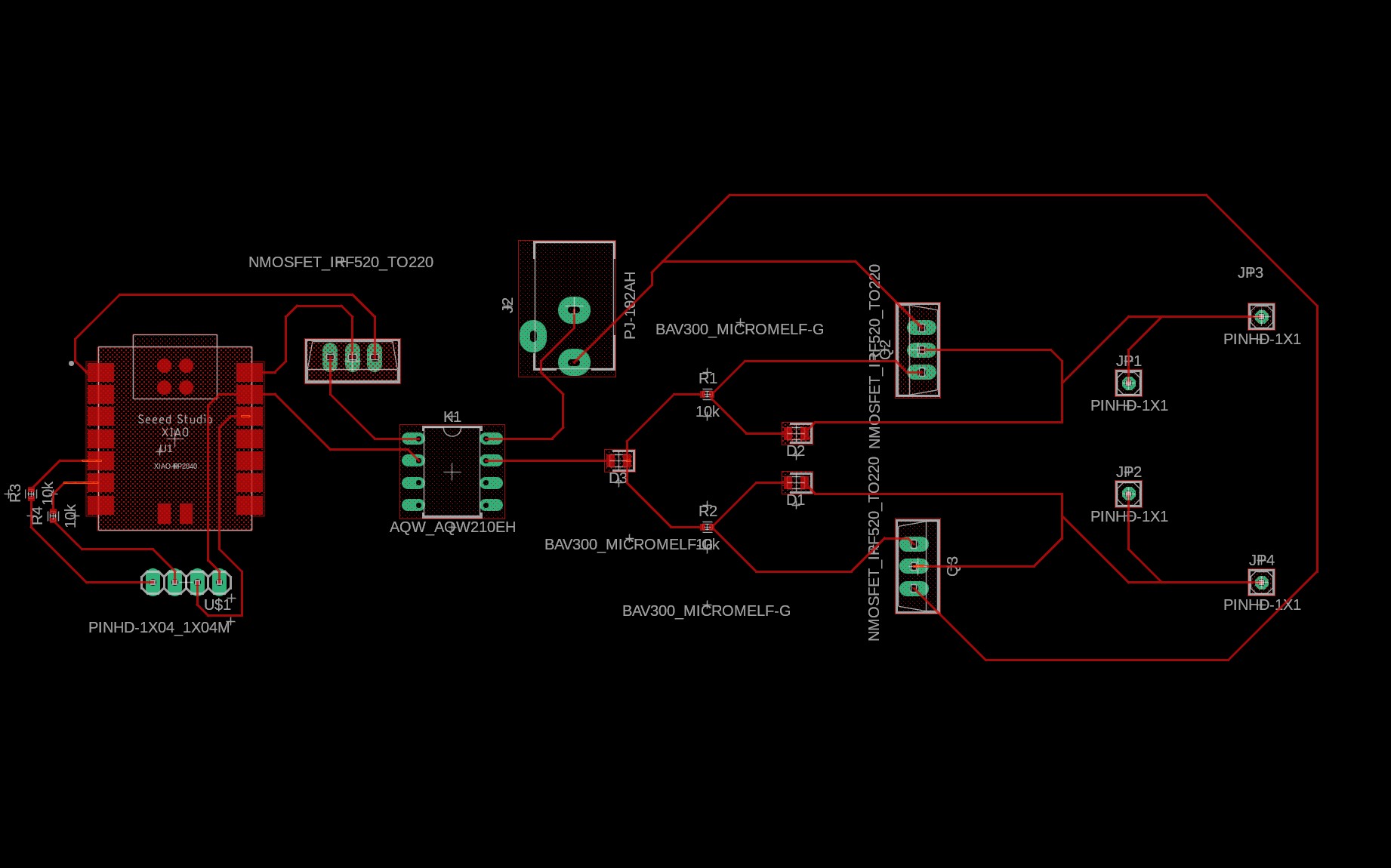
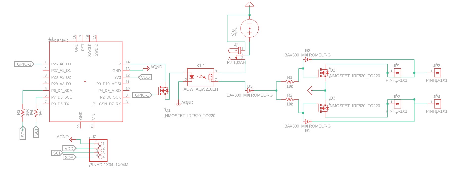
I spent too much time trying to understand how this circuit worked that I didn't have the time to properly size the capacitor and inductor. But, this isn't necessarily an issue, since I can include pins to swap out and experiment with different heating coils and capacitor banks: this may be benficial in tuning the performance of the circuit. All the control logic (e.g., Xiao interfaces, mosfets) can definitely be set in stone, leading to the following circuit that I made using Fusion 360.
The workflow using Fusion 360 was incredibly straightforward. I was able to connect all the relevant components with the following PCB design, maintaining all the components (including a 12-V input for the induction coil) on one side of the PCB. I'm looking forward to making this in the following week.