"There are only four rules you need to remember. Make the plan, execute the plan, expect the plan to go off the rails… throw away the plan." - Leonard Snart
So, the plan was to make the inductor heater circuit from last week. There was only one slight problem: the circuit I made last week had placeholder parts that didn't match what was available in shop - so my first step was to find appropriate parts and size them appropriately so that I didn't blow up the circuit. After all, nothing bad has ever happened from linking a bunch of capacitors together and forcing the current through a small wire, right?
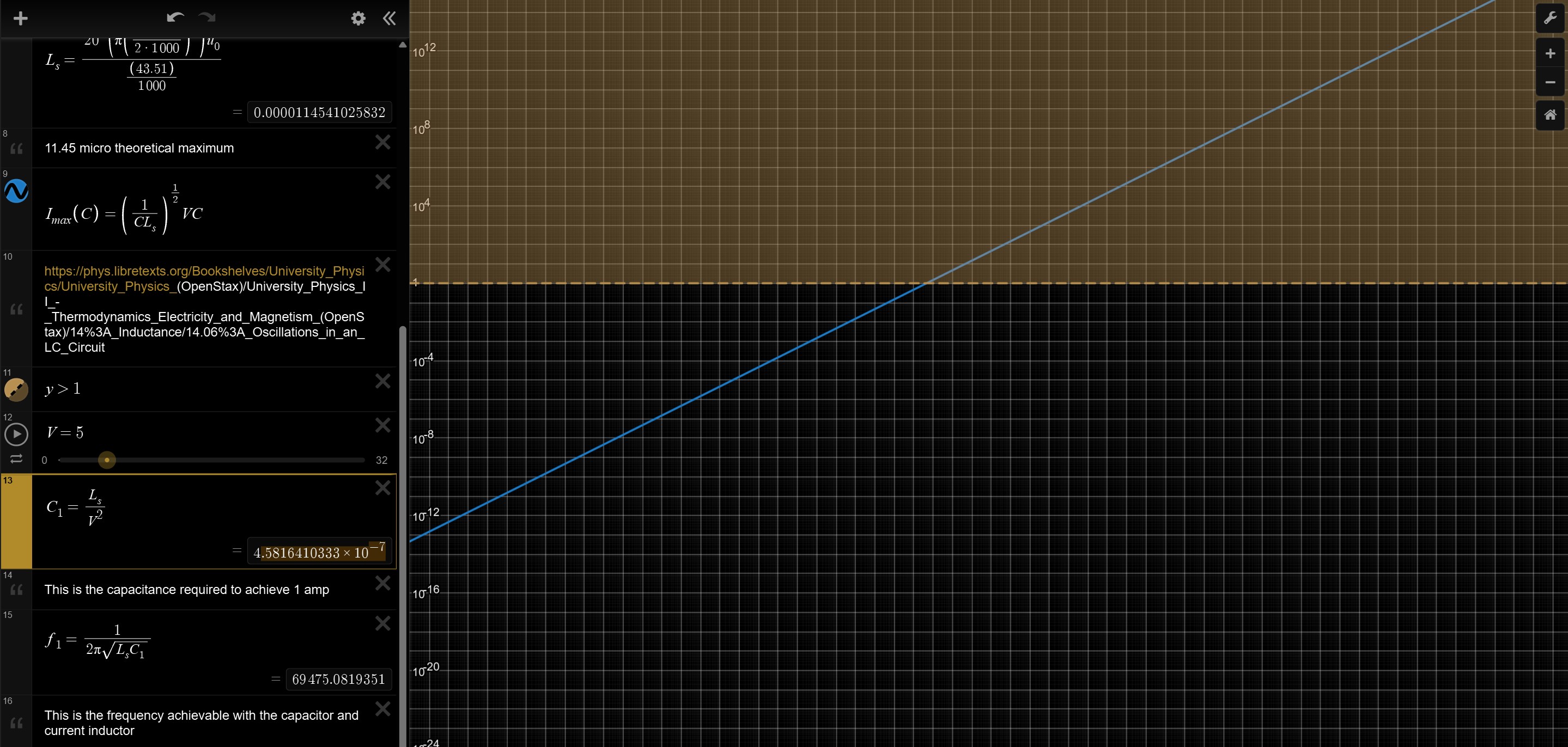
I created a little sizing tool in desmos so that I could get a target frequency of about 70 kHz with a 1-amp resonant current. The capacitors available were good enough (100 nF) to get the capacitance I needed. To get the corresponding inductance, I jankily made my own inductor using 22 AWG wire and hot glue... doesn't look pretty, but it get's the job done.
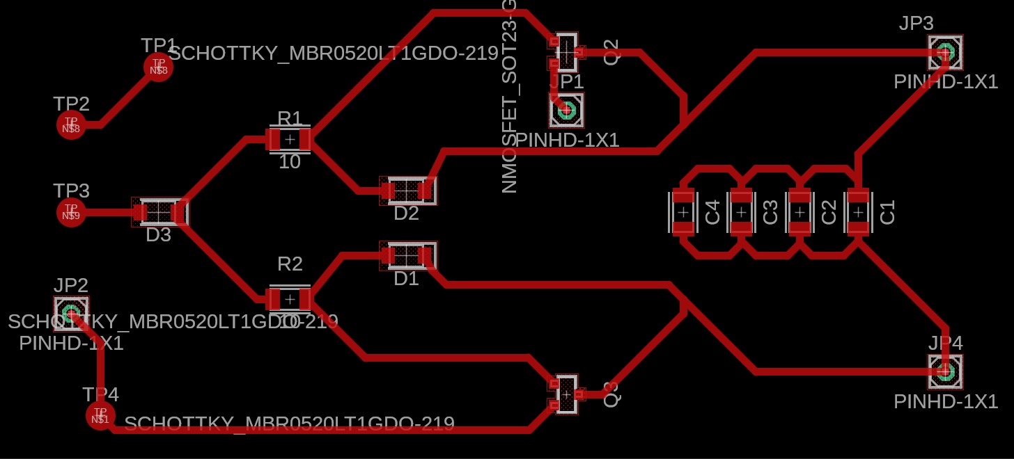
At first, manufacturing went pretty well: I exported my gerber and drill (.xln) files from Fusion, created a png using gerber2img, created the tool path using modsproject (selecting a 1/64" end mill), and uploaded my G-code to the carvera. A quick aside on gerber2img: the process worked best for me when I uploaded the .xln file with the outline of the board first, then locked the dimensions and origin, and then uploaded the .xln with the traces. For some reason, when I did the opposite, the scaling would be off. Anyway, back to my notes.
.jpeg)
I hooked up the circuit to five volts and... nothing happened.

I checked everything: there were no shorts, my diodes were oriented correctly, the voltage was live - but a telltale sign of the issue was the there was absolutely no current going through the circuit. And that's when I decided to go back to simulate the circuit. That's when I learned that I had put no way of initially charging the coil: current would, as it usually does, take the path of least resistance, which was around the capacitor bank and coils right through the n-type mosfets back to ground. As such, I did a little bit of messing around with the simulation, referenced a couple of other inductor circuits, and...
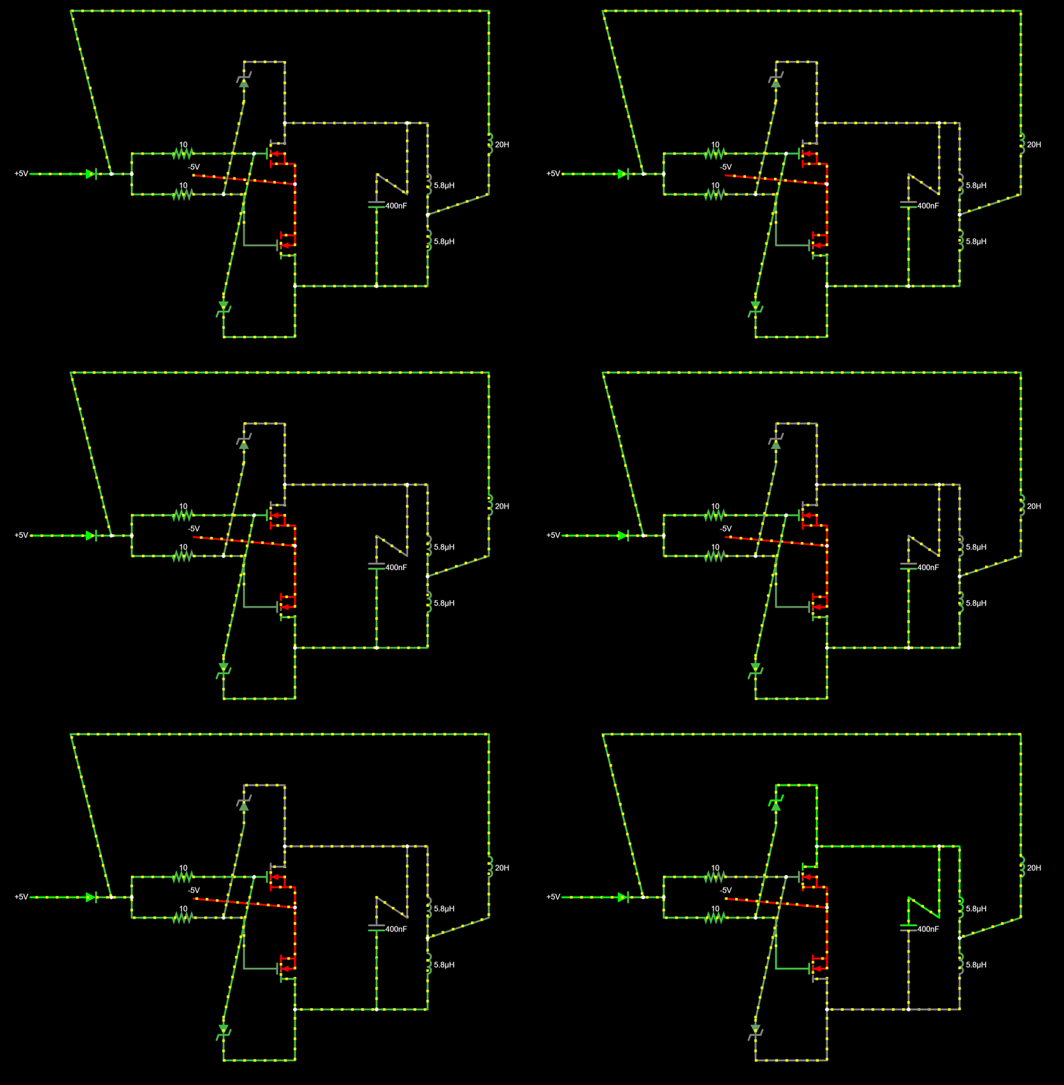
Huzzah! Time to remake everything...
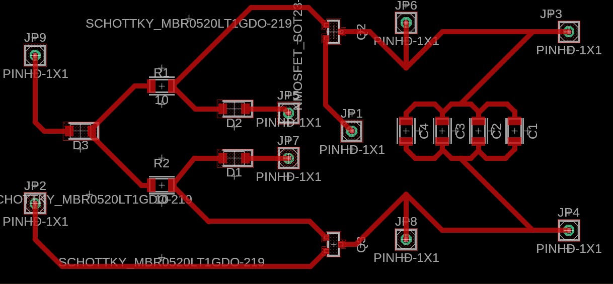
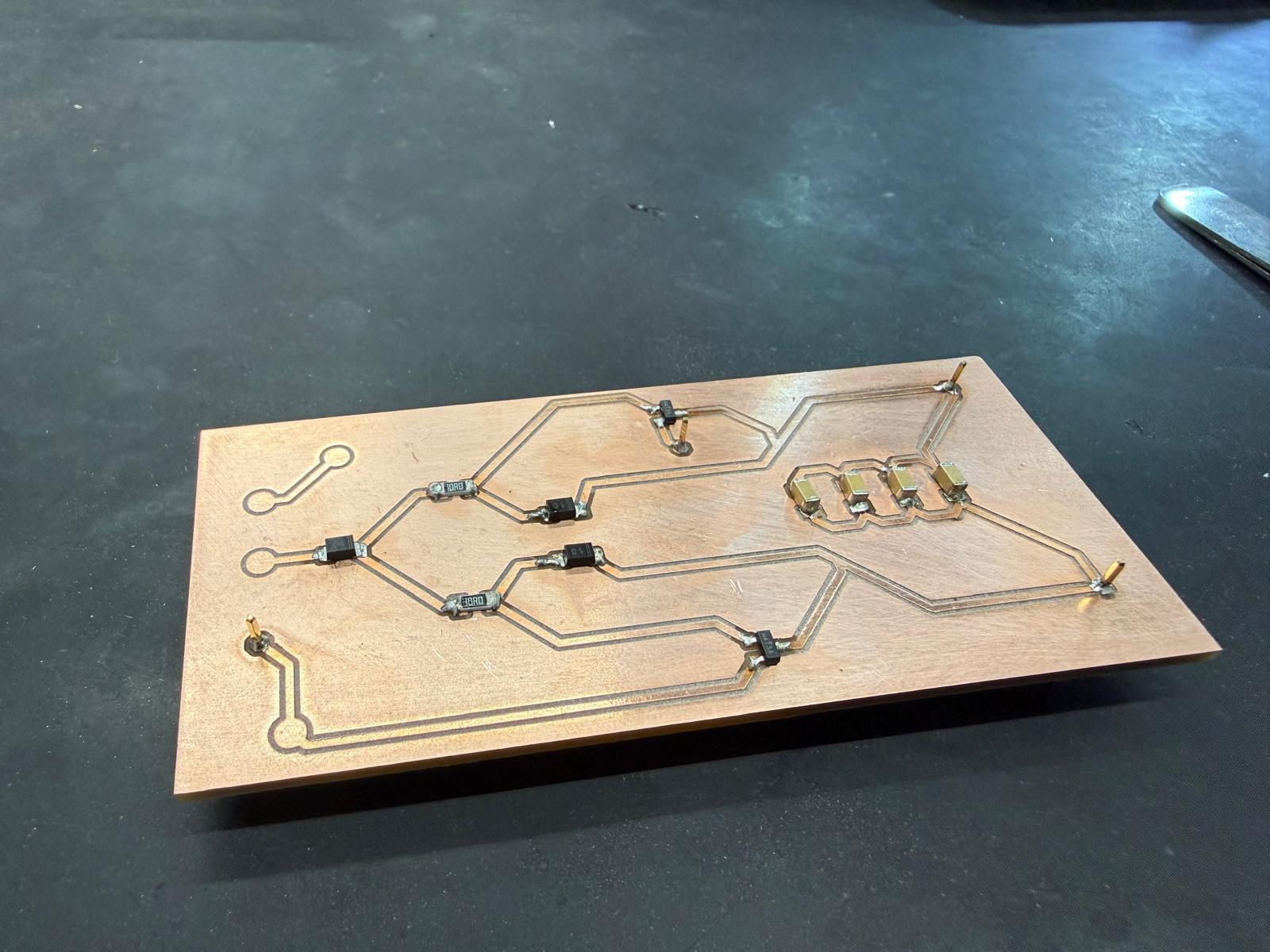
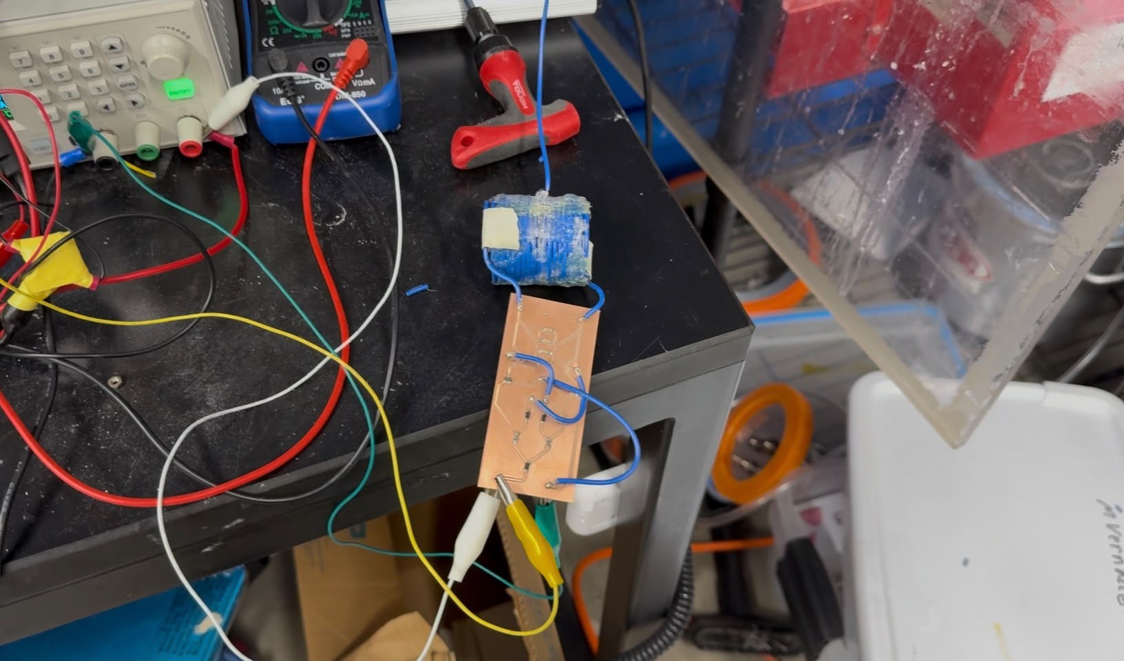
This time, current flowed through the board, but, I'm afraid that I still didn't manage to achieve resonance. The culprit this time? Fried mosfets. Whether they were friend before I turned on the power supply or after, I'm still not too sure, but I'll replace the fried MOSFETs later, ad it appears I have run out of time. Until next timme!