Week 5: PCB Design
Starting Out
Fablab Kicad Library was downloaded and installed from Fablab Kicad Library. Seeed XIAO ESP32-C6 was used for the PCB design for its bluetooth and WiFi capabilities from the recommendation from TA. To load XIAO Kicad Library, the step was referenced from https://fabacademy.org/2026/labs/zoi/xiaolibfix.html.
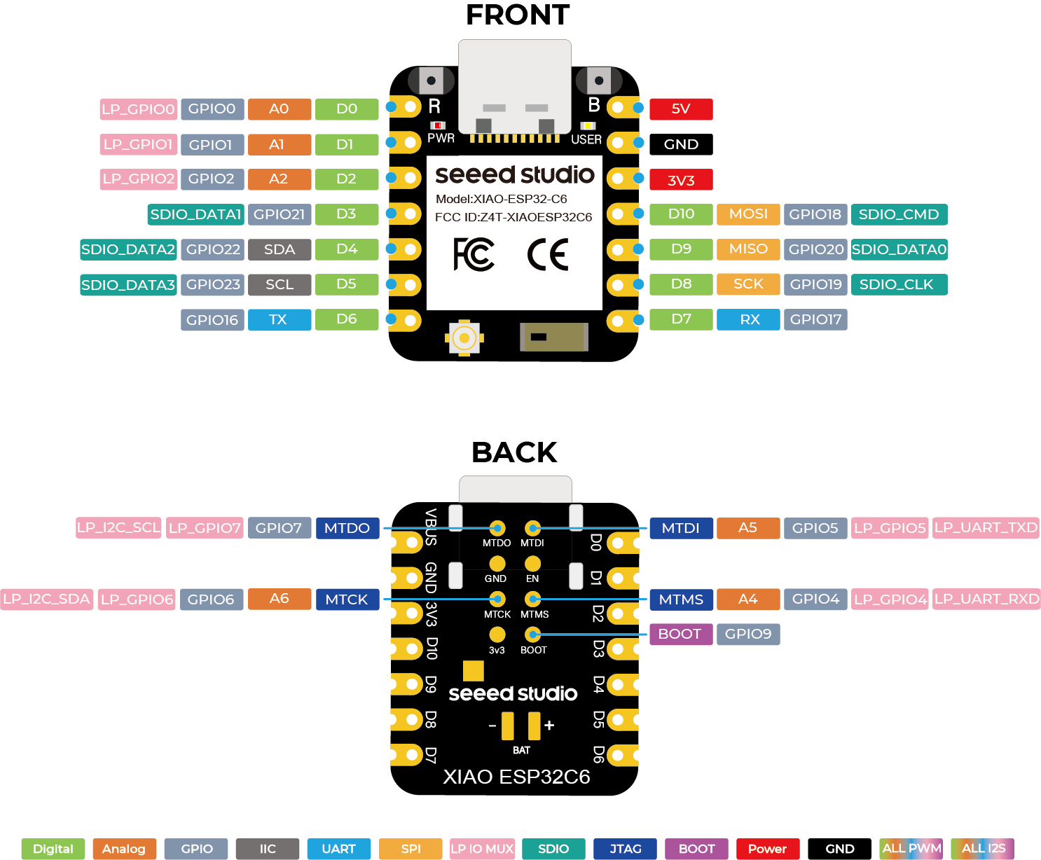
Seeed XIAO ESP32-C6
Design the PCB for Sparky
In order to design the PCB for Sparky, the ultimate function for Sparky is to be a remote-controlled car, with marble shooting, music playing, and LED lighting. Though multi-boards were recommended from TA. For this weeks assignment, I design a whole system on one board instead. Here is the structure of the system:
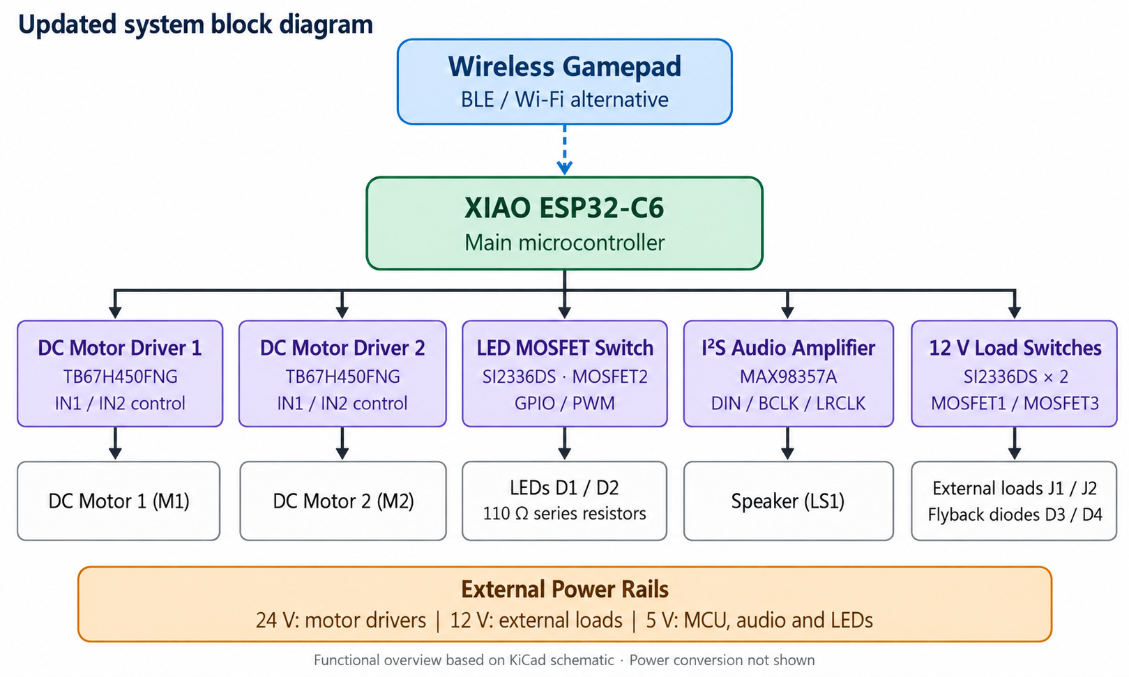
Design Structure
Basedon the provided inventory, the components for the PCB were selected as below, and the symbol as well as footprint of MOSFETs were imported from Digikey. All LEDs, capacitors, and resistors were used as standard symbols and footprints were used as the size of 0805.
List of Electronics Components
| Category | Part or Material | Qty | Notes |
|---|---|---|---|
| Control | Seeed Studio XIAO ESP32-C6 | 1 | U5. Main microcontroller for motor control, lighting, external loads, and audio. |
| Motor Control | TB67H450FNG,EL DC motor drivers | 2 | U2, U3. Control the two DC motors through IN1 / IN2 inputs; connected to the 24 V supply. |
| Drive | DC motors | 2 | M1, M2. Motor model, rated voltage, and current TBD. |
| Load Control | SI2336DS-T1-GE3 N-channel MOSFETs | 3 | MOSFET1 and MOSFET3 switch the external loads; MOSFET2 switches the LEDs. |
| Audio | MAX98357A I²S audio amplifier | 1 | U4. Receives DIN, BCLK, and LRCLK signals from the microcontroller and drives the speaker; powered from 5 V. |
| Audio | Speaker | 1 | LS1. Connected to the amplifier outputs. Impedance and power rating TBD. |
| Lighting | MP-3014-1100-50-80 LEDs | 2 | D1, D2. Controlled by MOSFET2, with individual series resistors. |
| Protection | Flyback diodes | 2 | D3, D4. Protection for the external switched loads. Diode part number and ratings TBD. |
| Resistors | 110 Ω resistors | 2 | R1, R2. LED current-limiting resistors. Power rating and package TBD. |
| Resistors | 100 Ω resistors | 3 | R3, R5, R8. MOSFET gate series resistors. |
| Resistors | 10 kΩ resistors | 3 | R4, R6, R7. MOSFET gate pull-down resistors. |
| Resistors | 100 kΩ resistor | 1 | R9. Connects the amplifier SD_MODE pin to the 5 V supply. |
| Capacitors | 0.1 µF capacitor | 1 | C1. Decoupling on the 5 V rail. Voltage rating and package TBD. |
| Capacitors | 10 µF capacitor | 1 | C2. Filtering on the 24 V rail. Select a suitable voltage rating. |
| Capacitors | Additional 5 V supply capacitor | 1 | C3. Capacitance is obscured in the schematic image. |
| Connectors | Two-pin connectors | 2 | J1, J2. Conn_01x02_Pin symbols for external 12 V loads. Connector pitch, current rating, and attached load types TBD. |
The circuit layout was drawn using KiCad, ensuring proper routing and signal integrity.
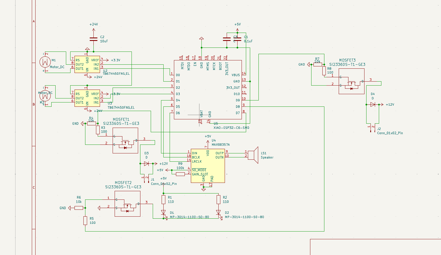
Schematic Editor 1.0
The footprint was messy and weird at the beginning and I found all the capacitor, resistor, and LED footprints were not linked.
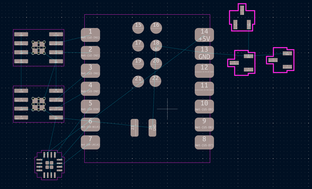
PCB Layout 1.0
The scheme was then edited during the design process and routing process.
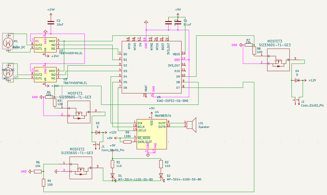
Schematic Editor 2.0
The final PCB layout was completed with proper routing and component placement, the motor and speaker were footprinted as two pin components. The 24 V and 5 V power supplies have not been footprinted yet.
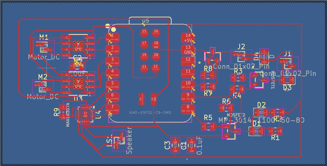
PCB Layout 2.0
After completing the design, the design rules were setup based on 2-layer service from OSHPARK and then checked.
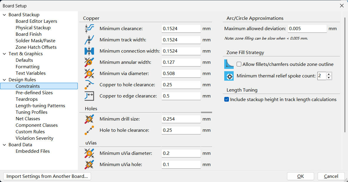
Design Rule Settings
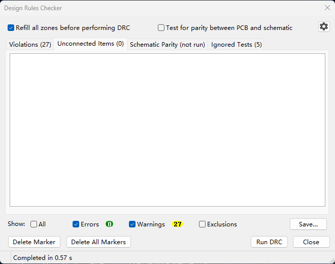
Design Rule Check
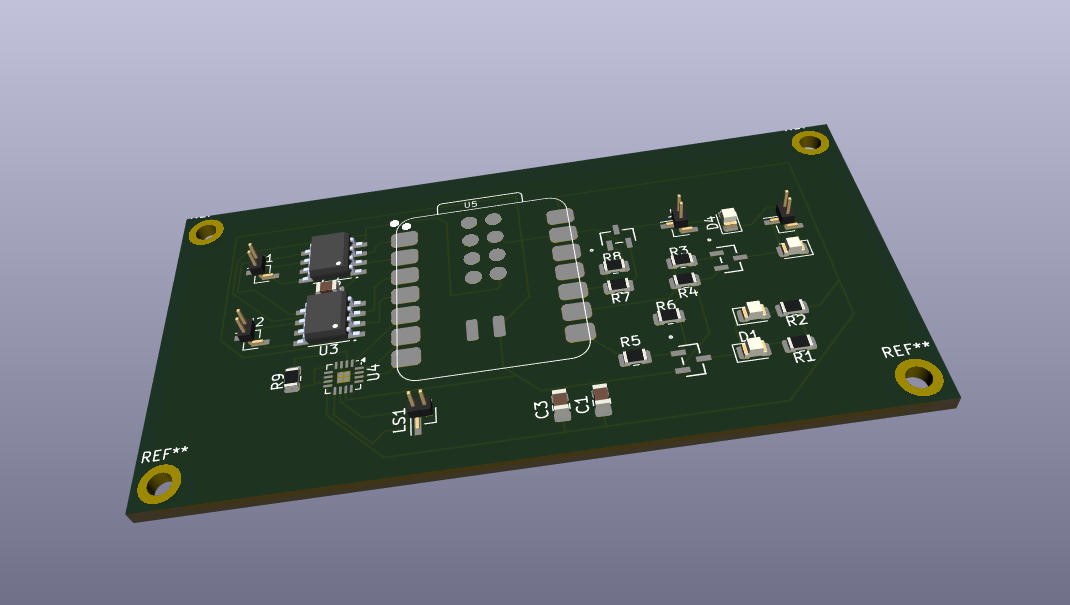
3D View of the PCB