make and test an embedded microcontroller system that you designed

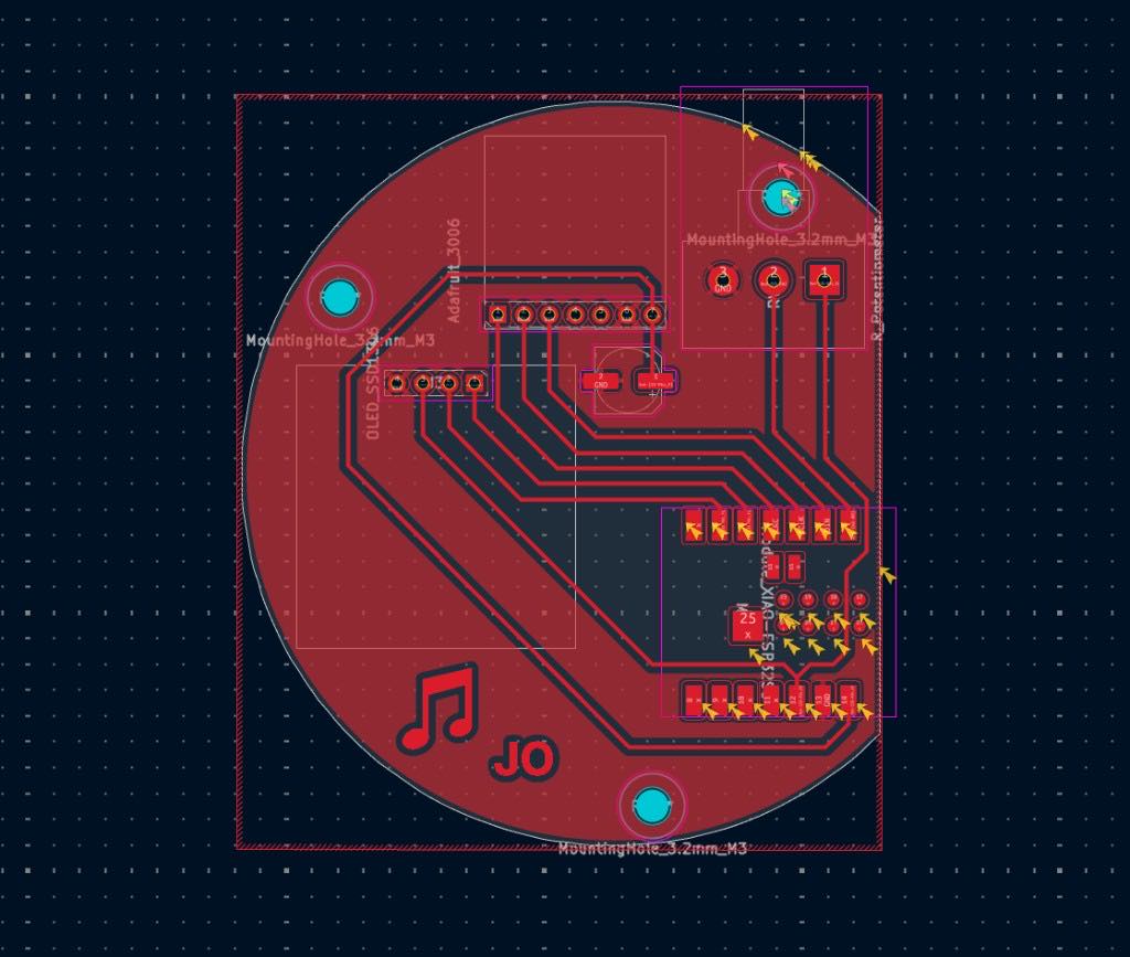
This was the final PCB design I settled on from last week's assignment!

Final circular PCB layout with the XIAO module, OLED and amplifier headers, a potentiometer, mounting holes, a music note, and JO

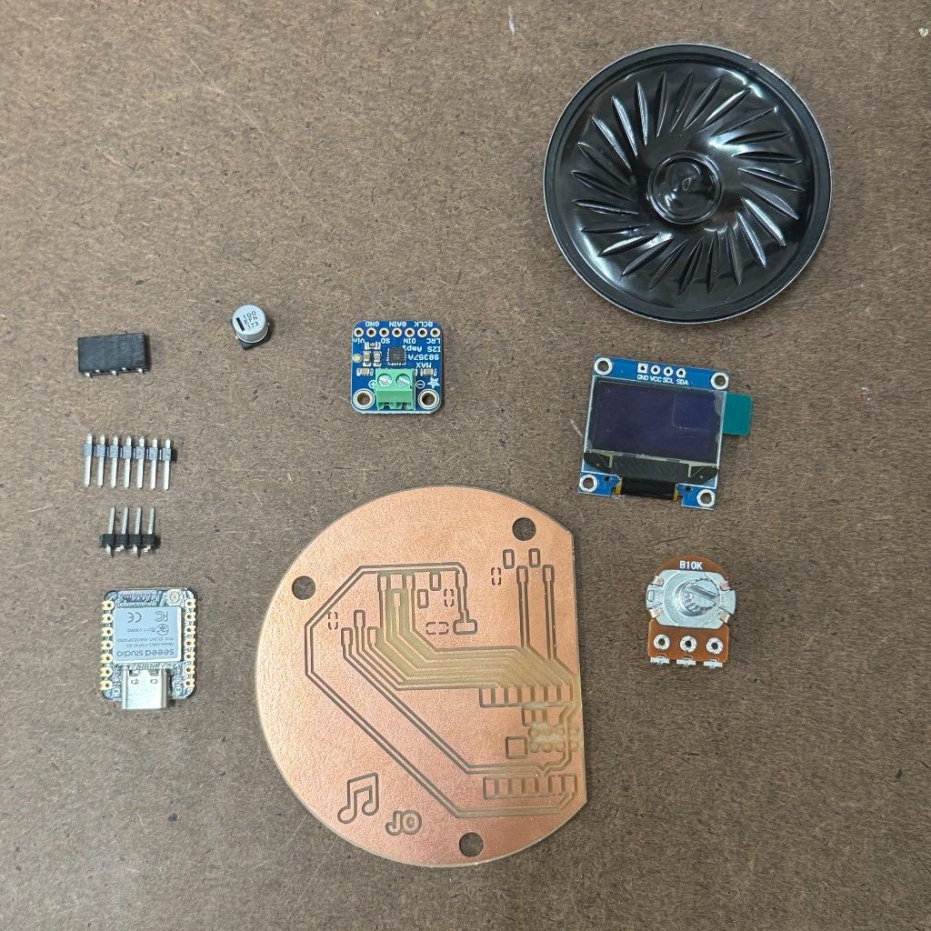
my final components

Name Datasheet
speaker datasheet
amplifier datasheet
microcontroller datasheet
potentiometer datasheet
oled screen datasheet
100uF capacitor datasheet
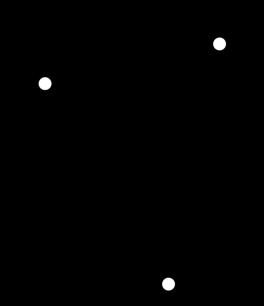
Board render with three white holes on a black background
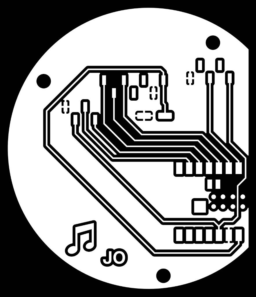
Black and white render of the circular board traces, pads, music note, and JO
White circular board outline on a black background
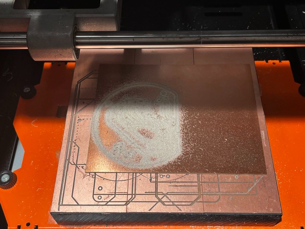
Copper board on the milling machine with the circular board being cut
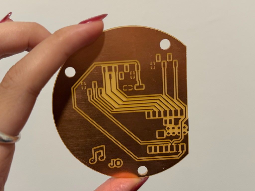
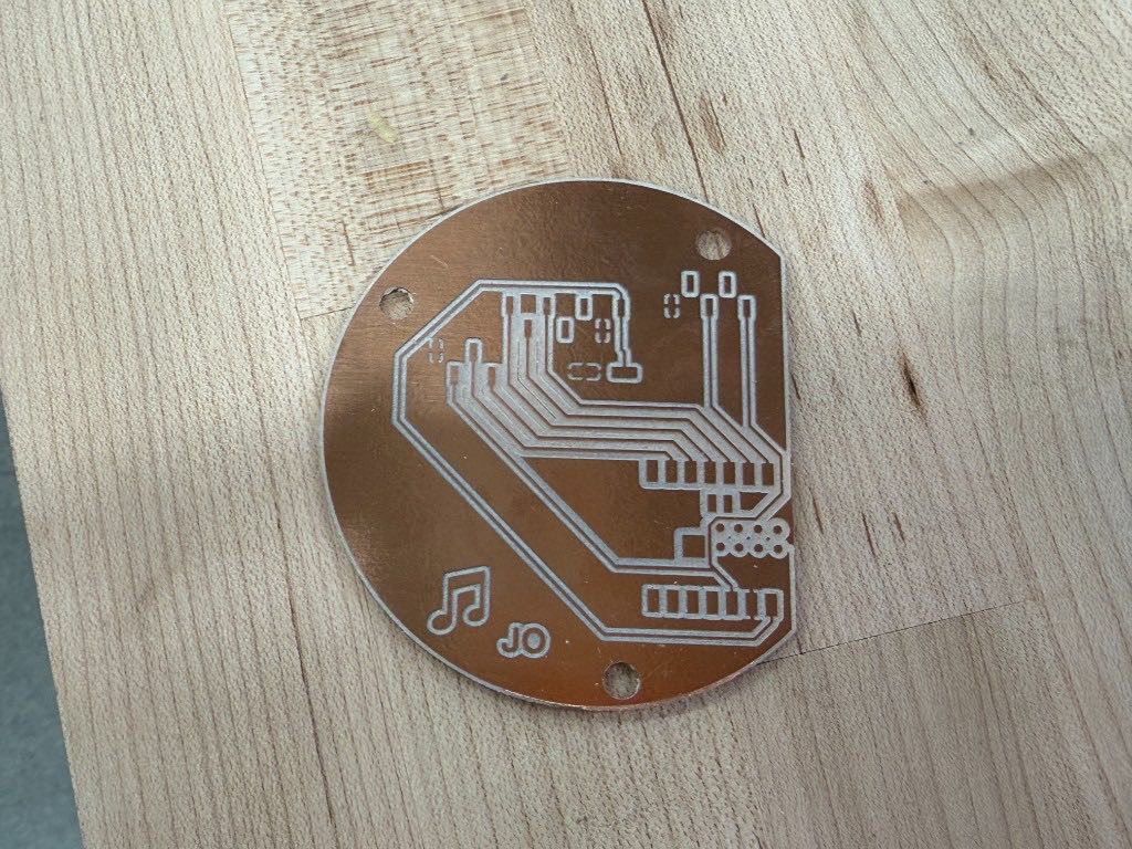
Hand holding the milled circular copper board with traces, mounting holes, a music note, and JO
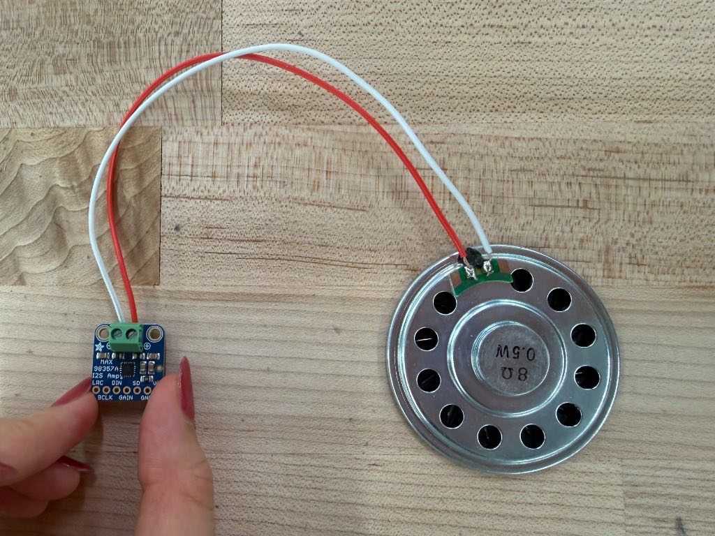
Amplifier breakout wired with red and white wires to a round speaker on a wood table
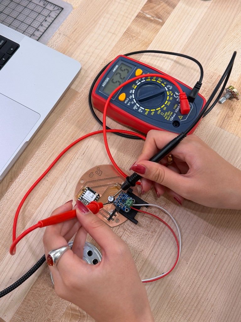
Testing the assembled board with a multimeter and probes
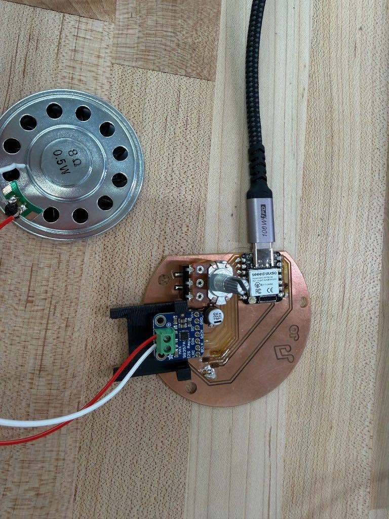
Assembled circular board connected to the speaker and a USB cable, with the XIAO, amplifier, potentiometer, and capacitor on it
Milled circular copper board with silver traces on a wood table
Milled board surrounded by its components: the XIAO, pin headers, capacitor, amplifier, OLED screen, potentiometer, and speaker
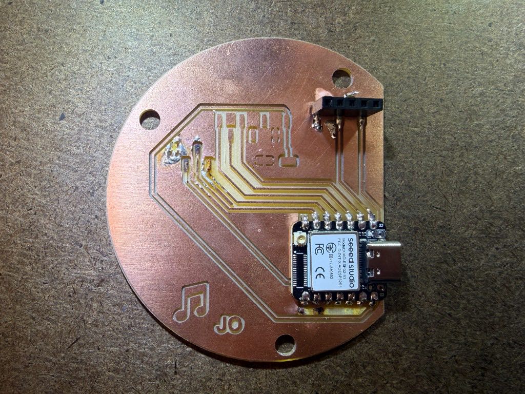
Circular copper board with the XIAO soldered on and a black pin header
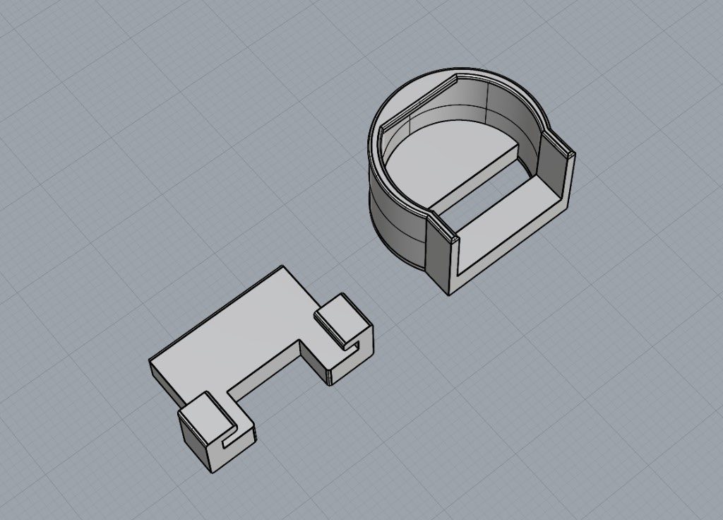
3D model of a circular enclosure and a flat bracket piece on a grid
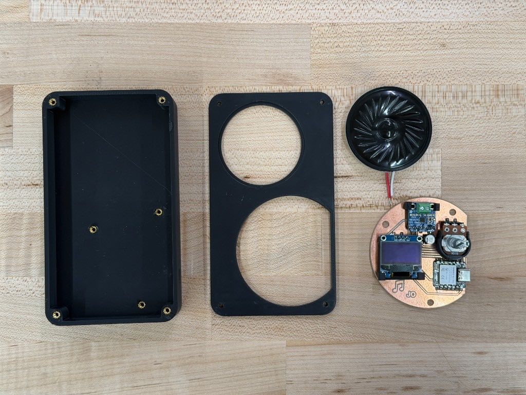
Black enclosure base and lid with two round cutouts, next to the speaker and the assembled circular board with the OLED screen on