3. Modular Fish
-
1. A Fish in Four Parts
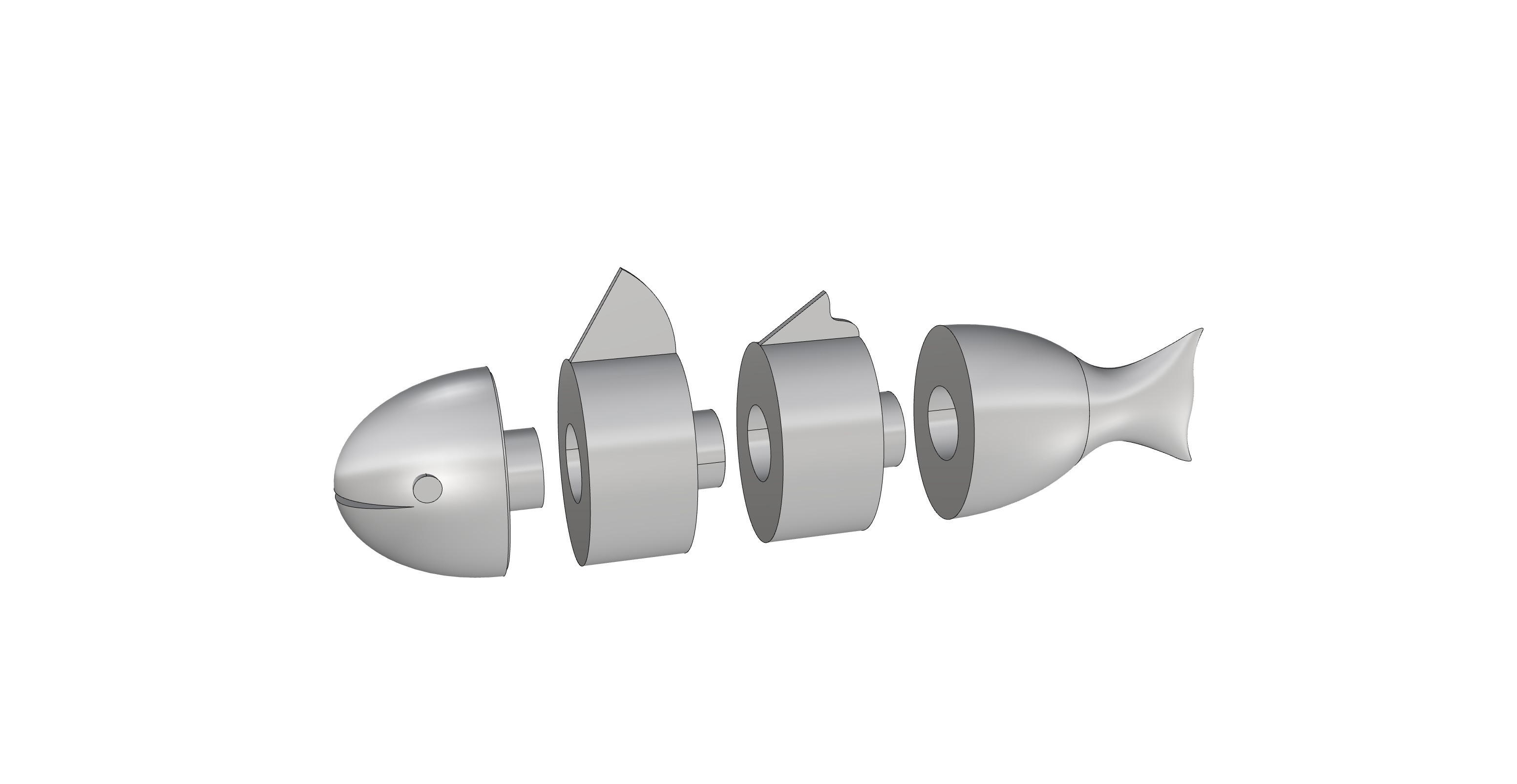
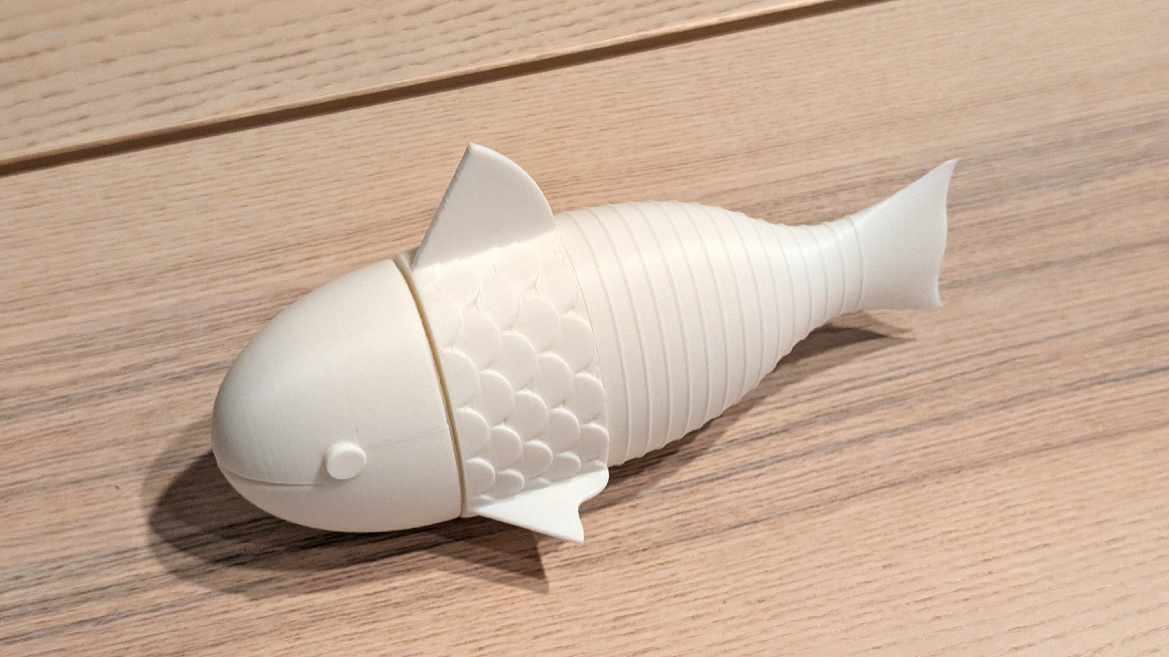
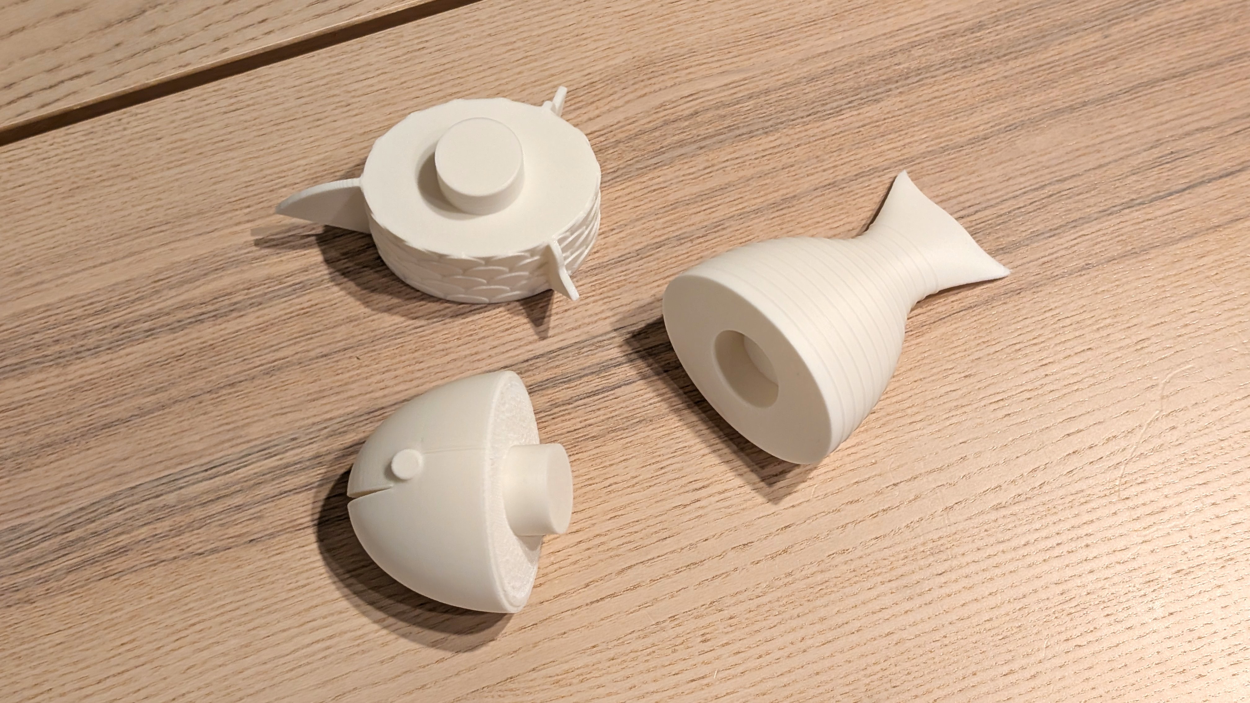
For this week’s assignment, I worked on a first model of a fish constructed in 4 parts. To begin, the parts of the fish that I wanted to use as variables for this first iteration were: the head, the fins, the gills, the skin, and the tail. To simplify the possible combinations, and to find a design language, I identified 4 parts: the head will be independent, there will be two body parts that will entail the skin, the fins, and the gills, and lastly, the tail, including the skin texture.
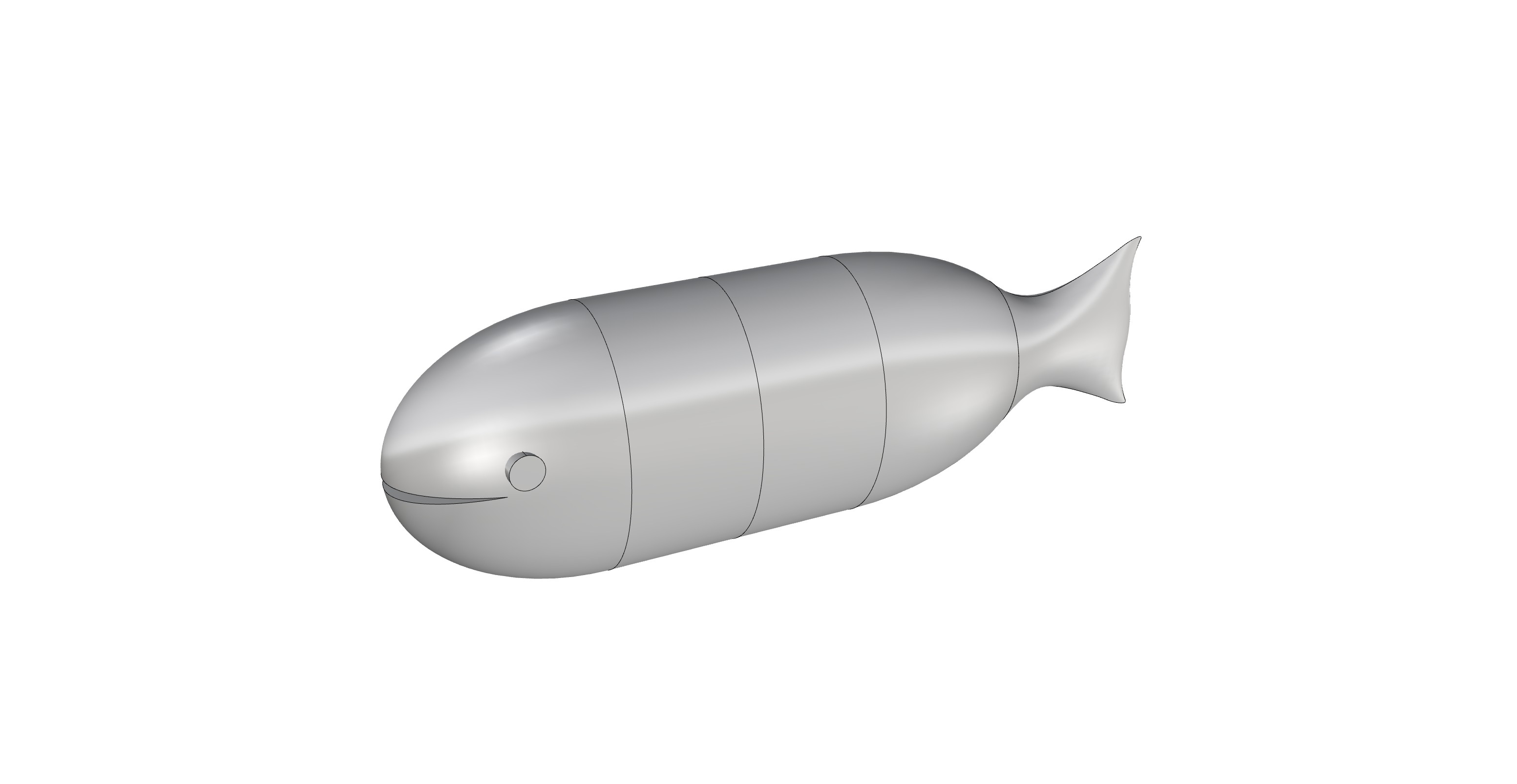
In terms of the design, I needed a front, a back, and a modular system for the length in between as the body, a bit like a hamburger, where you can fit as many layers of ingredients as you want in between the buns. This means that they have to follow roughly the same cross-section, and it’s only the front and the back that have a dramatic taper. The overall size of the fish is around the scale of a toy or a tabletop object, not so large that it becomes a piece of furniture, but not too small or delicate-looking to encourage sturdiness for play.
-
2. Press Fit and Texture
For the parts to come together, I wanted them to be press fit. The socket between parts is designed as a cylindrical knob so it looks like an oversized fish spine bone. For the spacing of the press fit, I used an offset of about 0.02mm between parts.
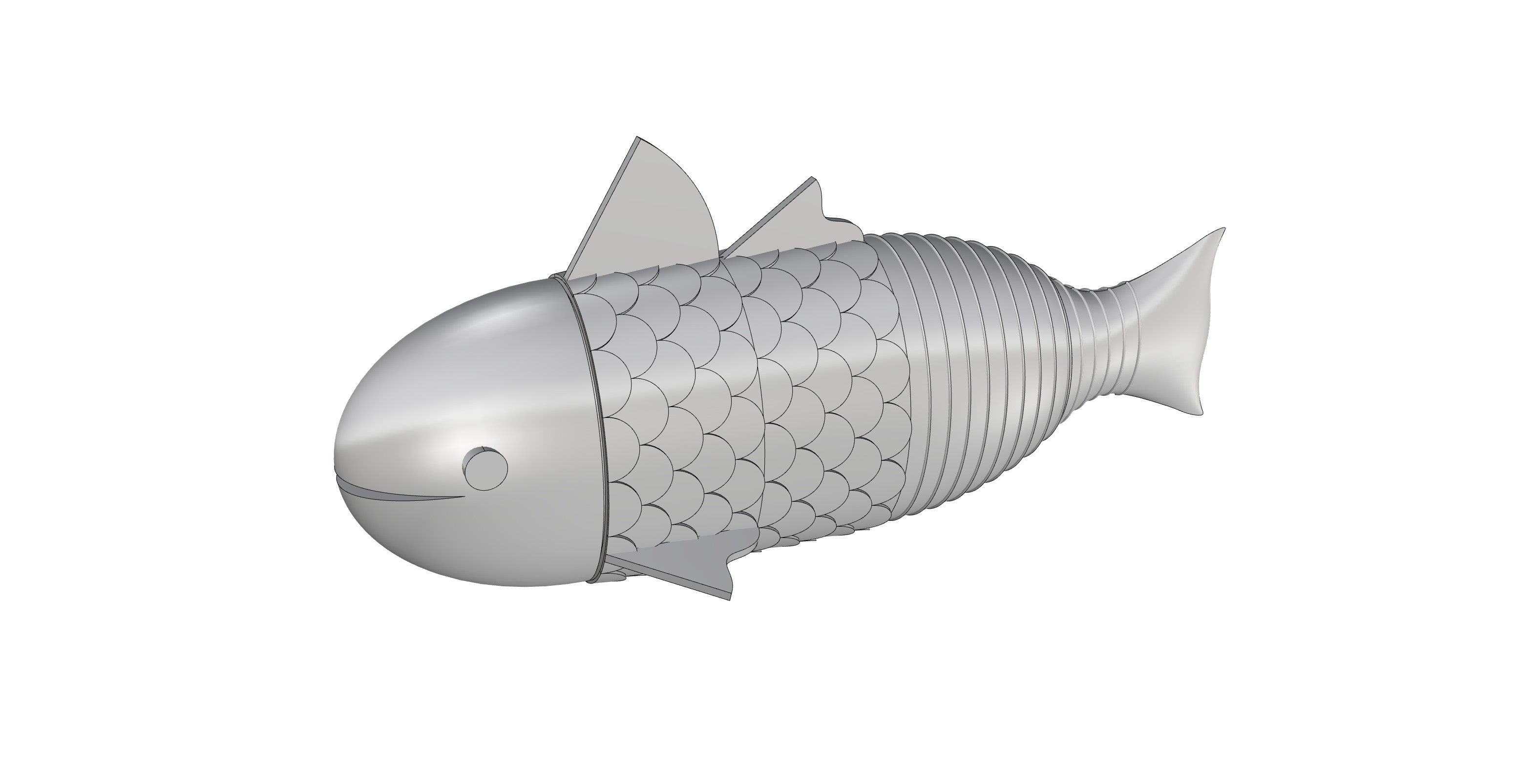
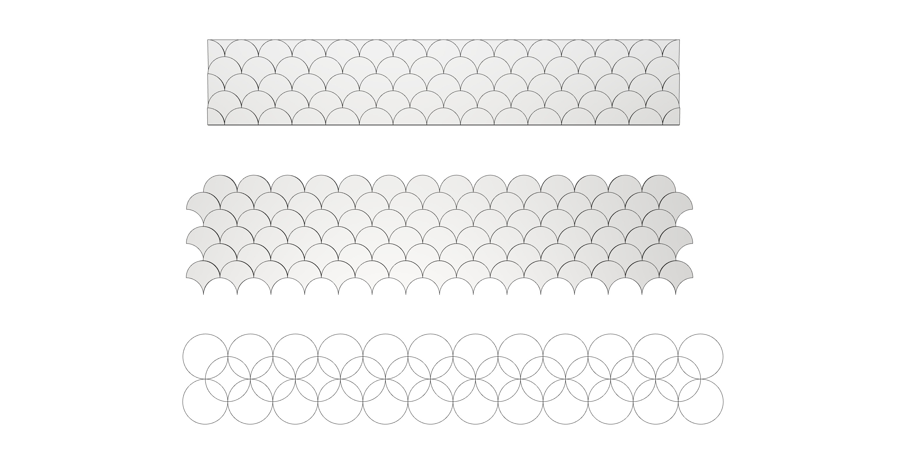
The texture is a challenging part on a streamlined body. For the in-between body layers, this is relatively easy because it is a continuous oval cylinder, where the fish-scale texture can be more complex and remain three-dimensional. For the tail, this requires parametric mapping on the tapering surface which also changes in scale. For this assignment, I decided to go with a simpler pattern through contouring in the direction of the taper, which provides a texture that transitions well toward the tail of the fish.
-
3D Model
-
3. Laying Out the Print
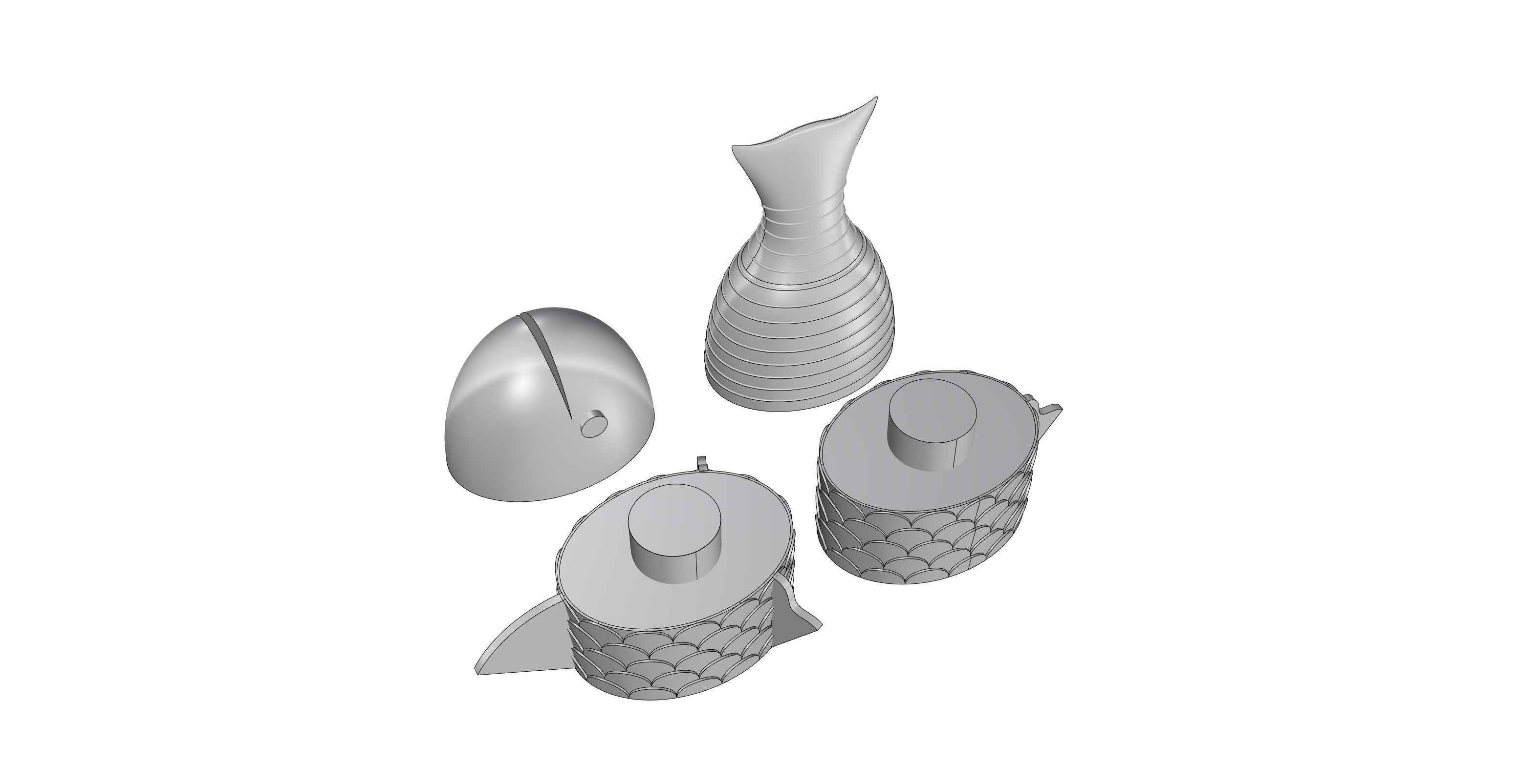
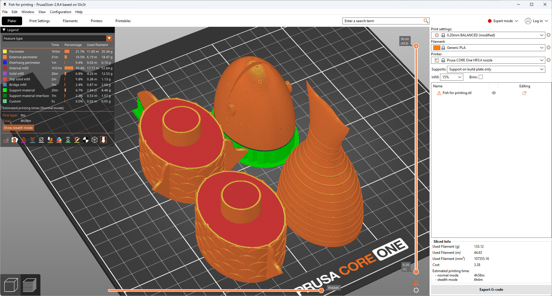
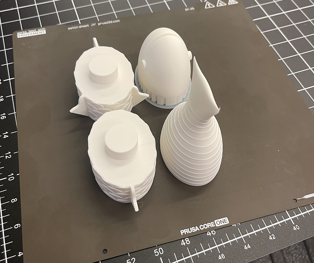
Since there are cross-sections on each part of the fish assembly, the straightforward method to position them on the printer bed is to place each chunk flat with the socket facing up. This minimizes the support needed and ensures the outside texture is printed as cleanly as possible. Once laid out, this looked a bit like a fishmonger’s table at the market.
-
4. Slicer Settings
I printed the parts on a Prusa CORE One with a 0.4mm nozzle.
Supports
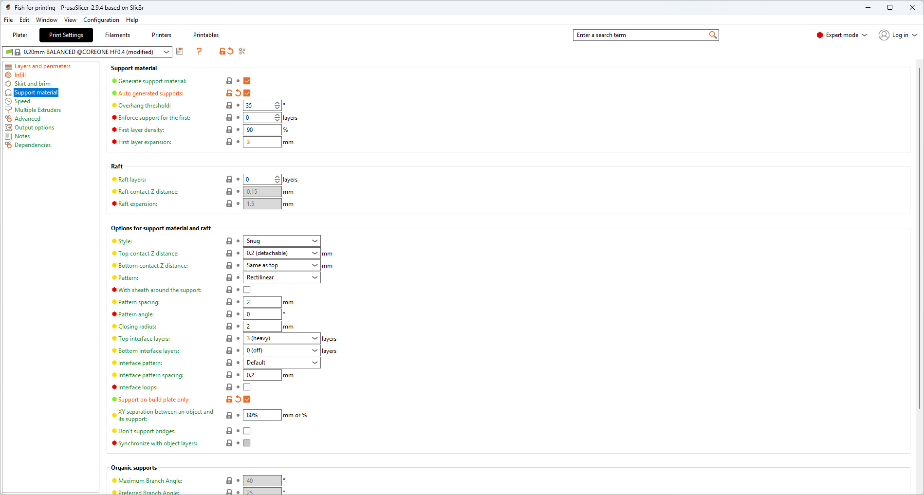
Because each part was laid flat with the socket facing up, only the overhangs needed support, so I used snug supports, which follow the outline of the part closely and are easier to remove without damaging the texture.
Perimeters
The slicer settings were driven by the fact that this is a toy rather than a display object: it will be picked up, dropped, and taken apart and put back together many times, so the strength of the print matters as much as how it looks. For that reason, I increased the perimeters from 2 to 3.
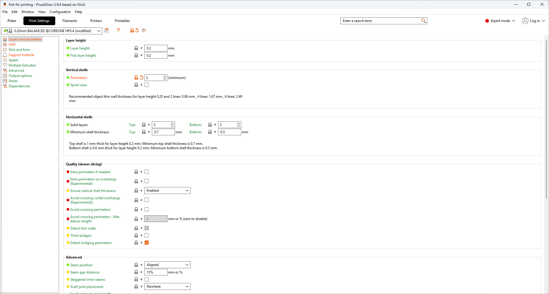
The outer wall is where the fish-scale texture lives, and since the texture is cut into the surface, it eats into the wall thickness; with only 2 perimeters, the deeper parts of the scales risk becoming thin or exposing the infill underneath. A third perimeter gives the texture enough material to sit in and makes the surface more resistant to wear. The extra wall also reinforces the sockets, which take the most stress in the assembly, since every press fit pushes outward on the socket walls and repeated assembly would eventually crack a thin shell.
Infill
For the infill, I used gyroid at 15%.
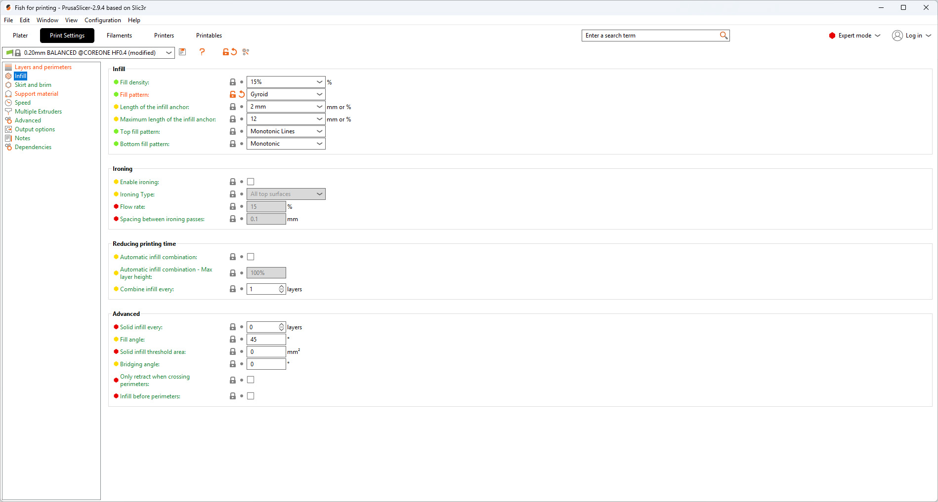
Unlike a static object that is only loaded in one direction, a toy gets pressure from every side, and gyroid’s continuous, wave-like structure distributes force evenly in all directions without the weak planes that grid or line infill can have between layers.
-
5. First Print
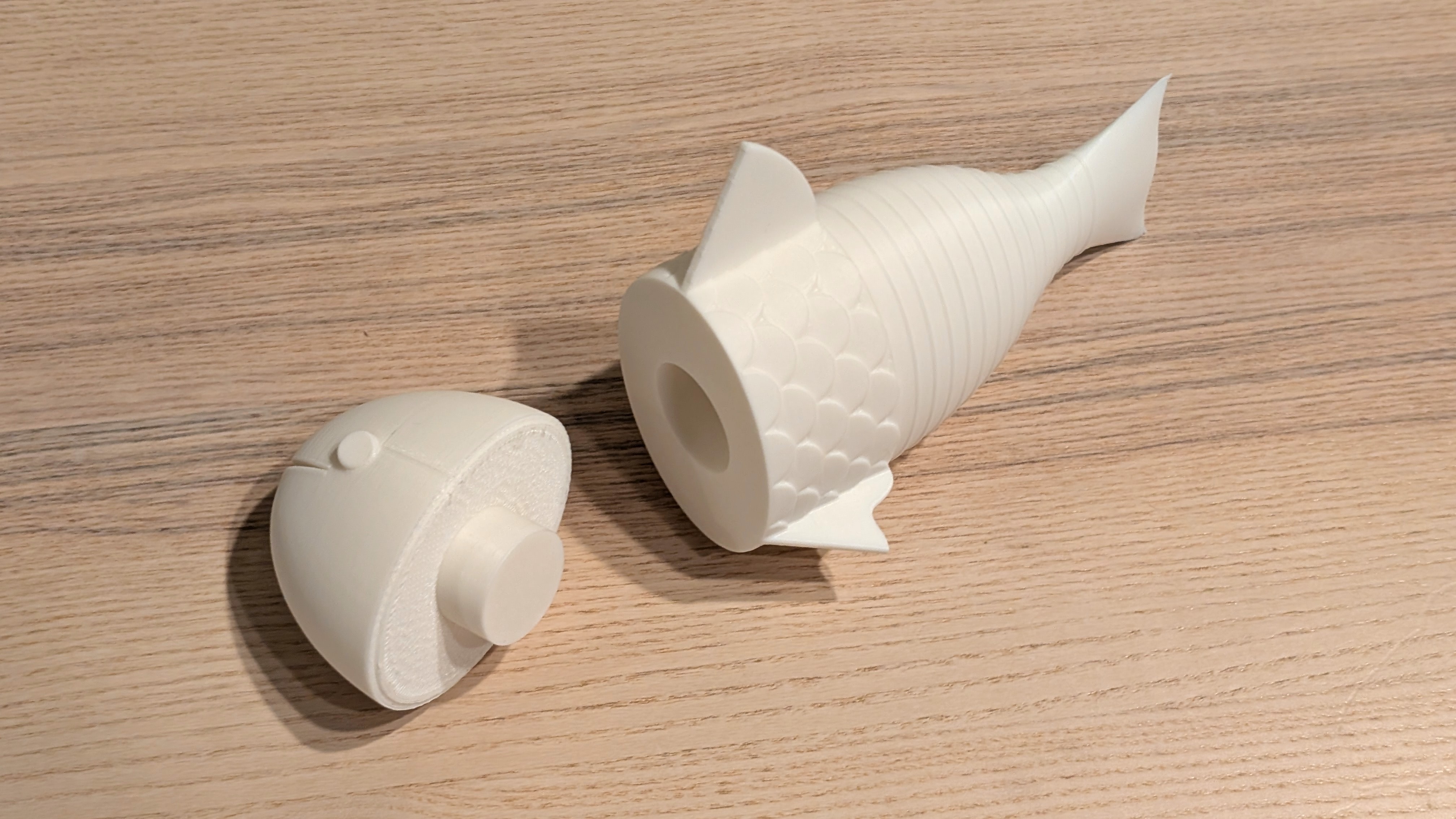
The first print of the fish was mostly successful.
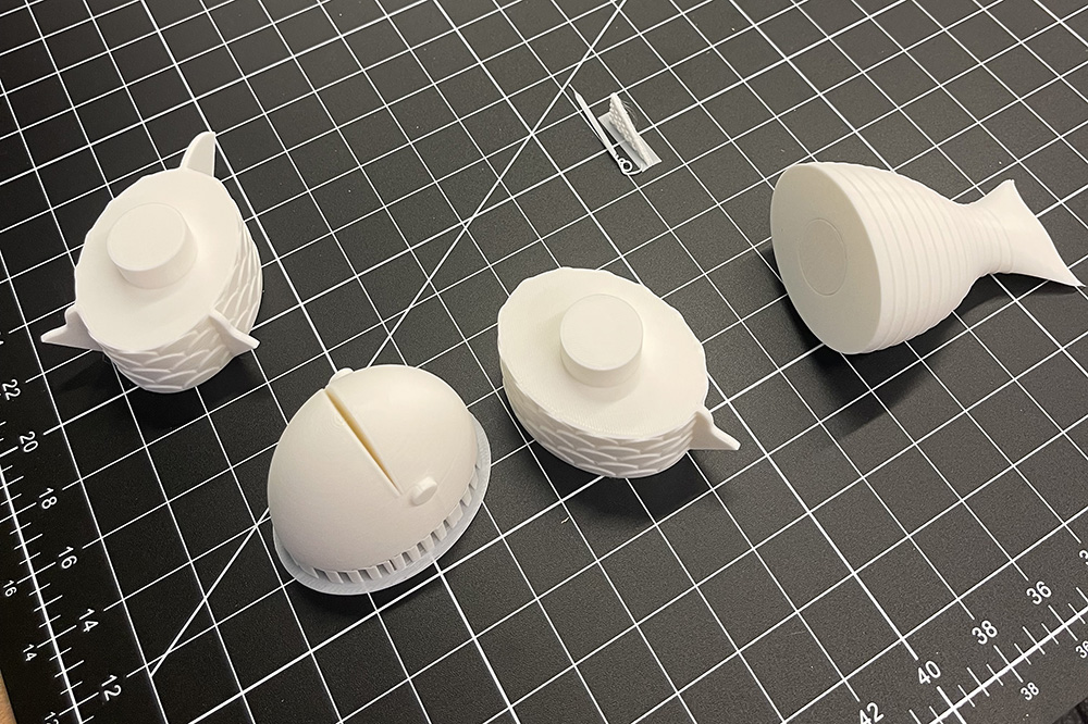
The main issue was the consistency of the sockets for the press fit. Even though they all share the same tolerance (0.02mm), some of them fit better than others, so the next steps would be testing other materials and geometries of connections. Instead of a cylindrical socket where the parts can rotate around the center axis, a small triangle can be added to the “spine” to stop unwanted rotation, while further reinforcing the idea of a bone in the fish. Another improvement will be to taper or round the socket so that it fits more easily. There are also a few sharp edges on the fins and the tail that will require a different geometry or fabrication method.
-
Result
-
6. 3D Scanning
For the scanning part of the assignment, I scanned a hippo toy with a Creality scanner.
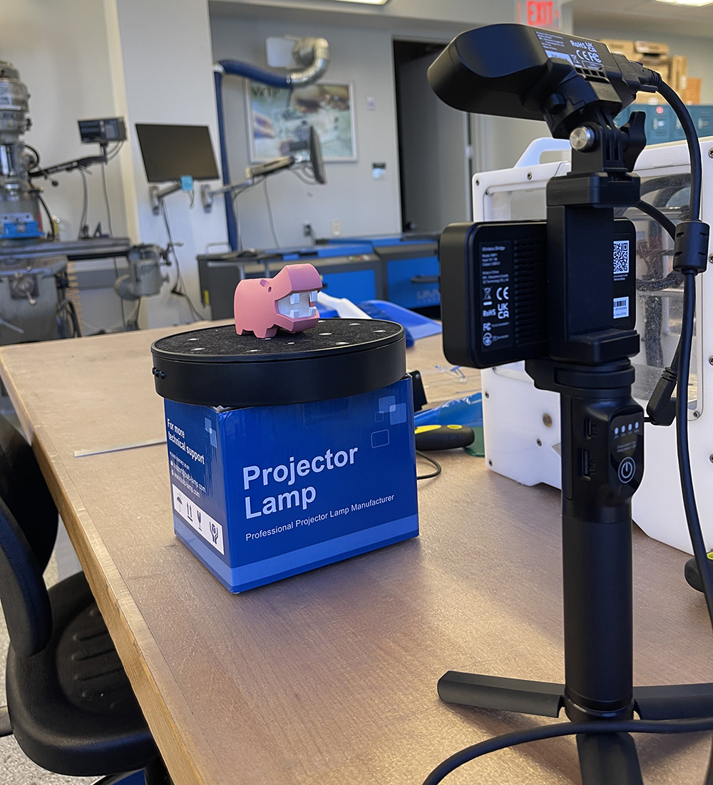
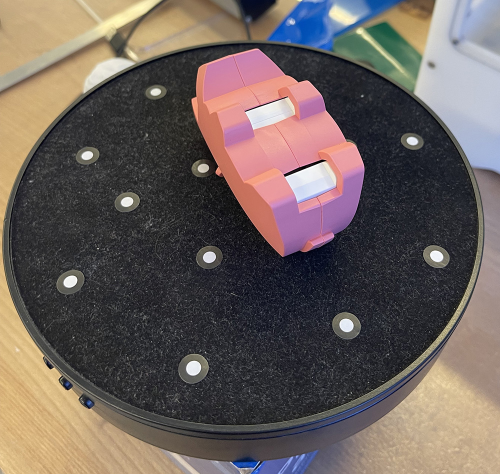
The toy is made by HalfToys and is a three-dimensional magnetic skeleton puzzle.
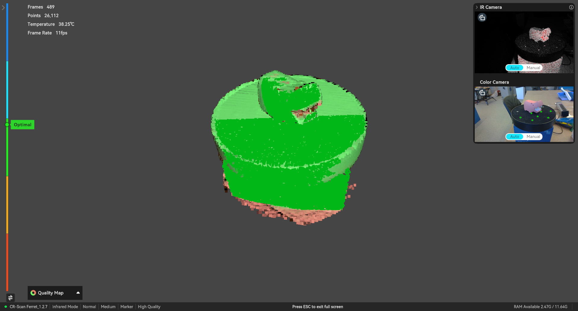
I scanned both sides of the toy and aligned the scans.
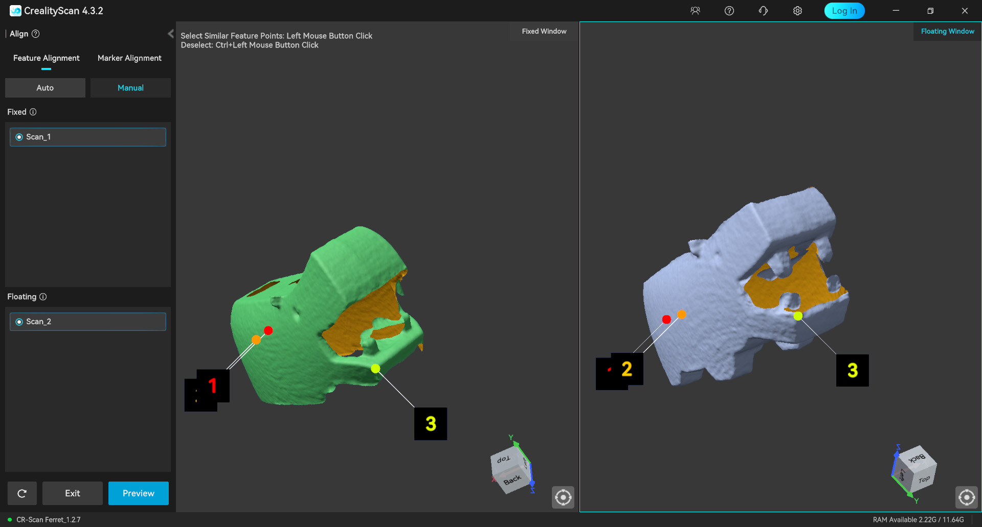
I will still need to do post-processing of the mesh model because there are a few parts that are missing and I wasn’t able to scan.
-
Scanned Mesh
-
AI Usage
Identifying AI usage
I used Claude (Anthropic’s AI assistant, model Claude Opus 5.5) to build the HTML for this page. I wrote the project text and made the fish model, the prints, the scan, the photos, and the 3D files myself. AI was not used to design the fish, the press-fit tolerances, or the slicer settings.
How AI was used
I used Claude in VS Code to build the page template, including the 3D model viewers.