Abstract
First steps with computer aided design.
The theremin is the world’s first electronic musical instrument, invented in the 1920’s by Leon Theremin. The coolest part about it is that it is played without touching it! The tone and volume it produces depends on the position of the player’s hands with respect to two antennae that stick out of the theremin. The sounds it produces are quite eerie, in part due to the smooth transitions between tones rather than the discrete jumps between different notes in conventional musical instruments. Here is a particularly skilled performance on the theremin, that made me fall in love with this instrument.
A theremin on Amazon costs about 400 dollars, which was too expensive for me to consider buying, but I think it is a perfect project that combines electronics, design, and manufacturing, and also exciting for my physics background. It seems like other people in the history of this class have thought of the theremin before as either a final project or borrowed inspiration for a weekly assignment. I will try not to borrow too much inspiration from them as I really want to make it my own.
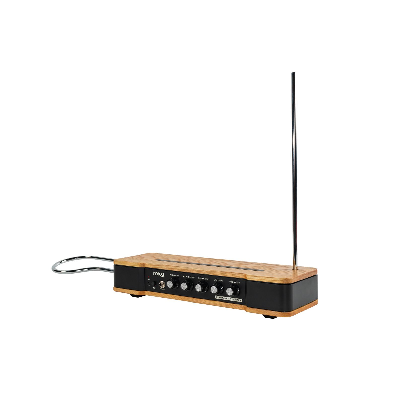
A theremin is usually made out of three parts:
- A body, which contains all the electronics.
- A vertical, open-ended antenna, that the singer uses to adjust the pitch of the sound. Effectively, by moving a hand around the antenna, the capacitance and the fundamental frequency of the circuit will change.
- A horizontal, looped antenna on the side, which is used to adjust the volume of the sound emitted. The closer the hand of the artist, the louder the sound will be.
There are many designs for the theremin and, as far as I understand, the choices are mostly aesthetic. The one I chose to be inspired by is a classic from Moog Etherwave.
Below is a preview of my Theremin, synced to my AutoDesk CAD file. It still has some components that need to be added, like a few of the switches in the front and back. For now, I chose to focus on the body, the antennae and the knobs.
Roughly, the work flow when creating the model was the following:
- Start from rectangular sketches for the metallic body and the two wooden panels on the top and bottom.
- Use cutting to create the slot in the front panel where the knobs go.
- Create knobs as equally-spaced cylinders with equal radius. Use smaller cylinders (with “Circular arrangement”) around the perimeter for cutting out the knob rugged edge.
- Create the top antenna as three concentric cylinders, of same length, stacked on top of each other.
- Create the bottom antenna using the perimeter of a rectangle and of half a circle, together with the sweep function in Autodesk.
As I did not have access to a technical drawing of this theremin model, all physical dimensions in this model are estimates. Each of them has been introduced as an adjustable parameter, that I may modify as I proceed with creating the actual theremin. In particular, I believe that, depending on the exact way the acoustics is implemented, the physical dimensions of the body may matter in terms of its acoustic resonances.The exact shape and sizes of the antennae will definitely influence their capacitance and hence the sound pitches generated through the electronics.