Abstract
Milling and assembling a circuit board.
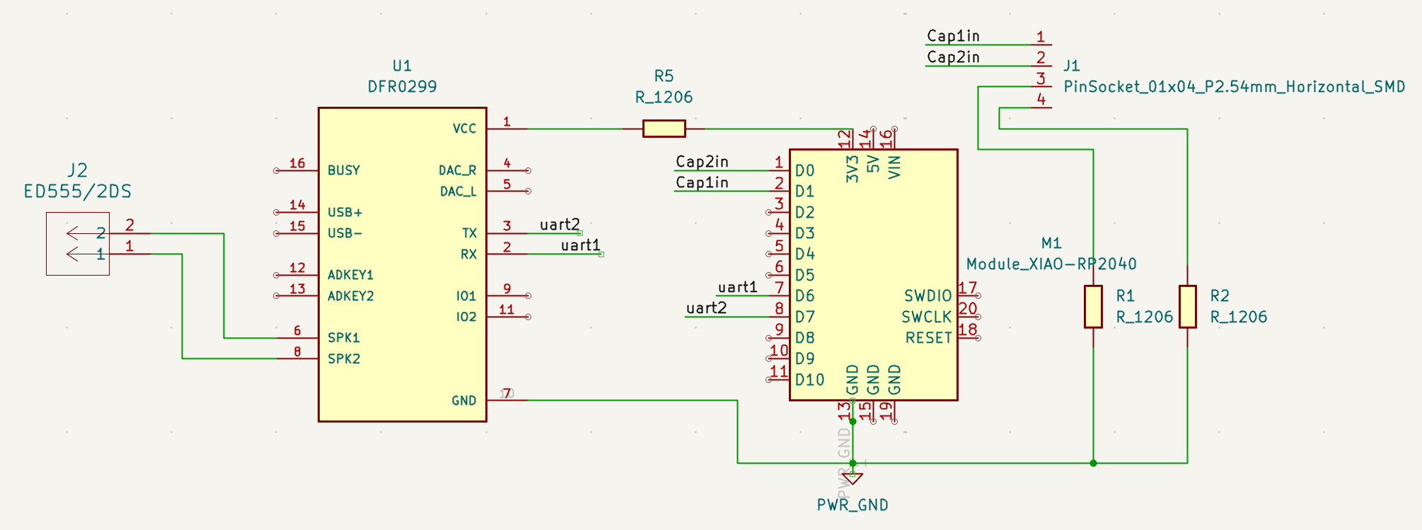
For this week’s assignment, we turned the PCB designed in week 5 into reality. For me, however, the recitation and review of week 6 turned out to be quite insightful. In particular, I realized that my board schematic and design had to be changed. The MP3 player and the microcontroller, using the UART communication protocol, had to be properly wired in order to make sure data transmission occurred correctly. Last week, I connected together all pins that had the same labels: the RX pins were connected to each other, as well as the TX pins. During the recitation I found out that this was not the correct way to do it: the RX pin of one device has to be connected to the TX pin of the other device, and vice versa. This meant, for my board design, that some wires got (badly) tangled up. No matter how much I moved components around, there were always at least two wires crossing. For that reason, I decided to add a 0 Ohm resistor along the 3.3V power supply path between the microcontroller and the MP3 player, “jumping over” one of the UART paths. The board schematic and layout are available here and here, and are shown as pictures below.
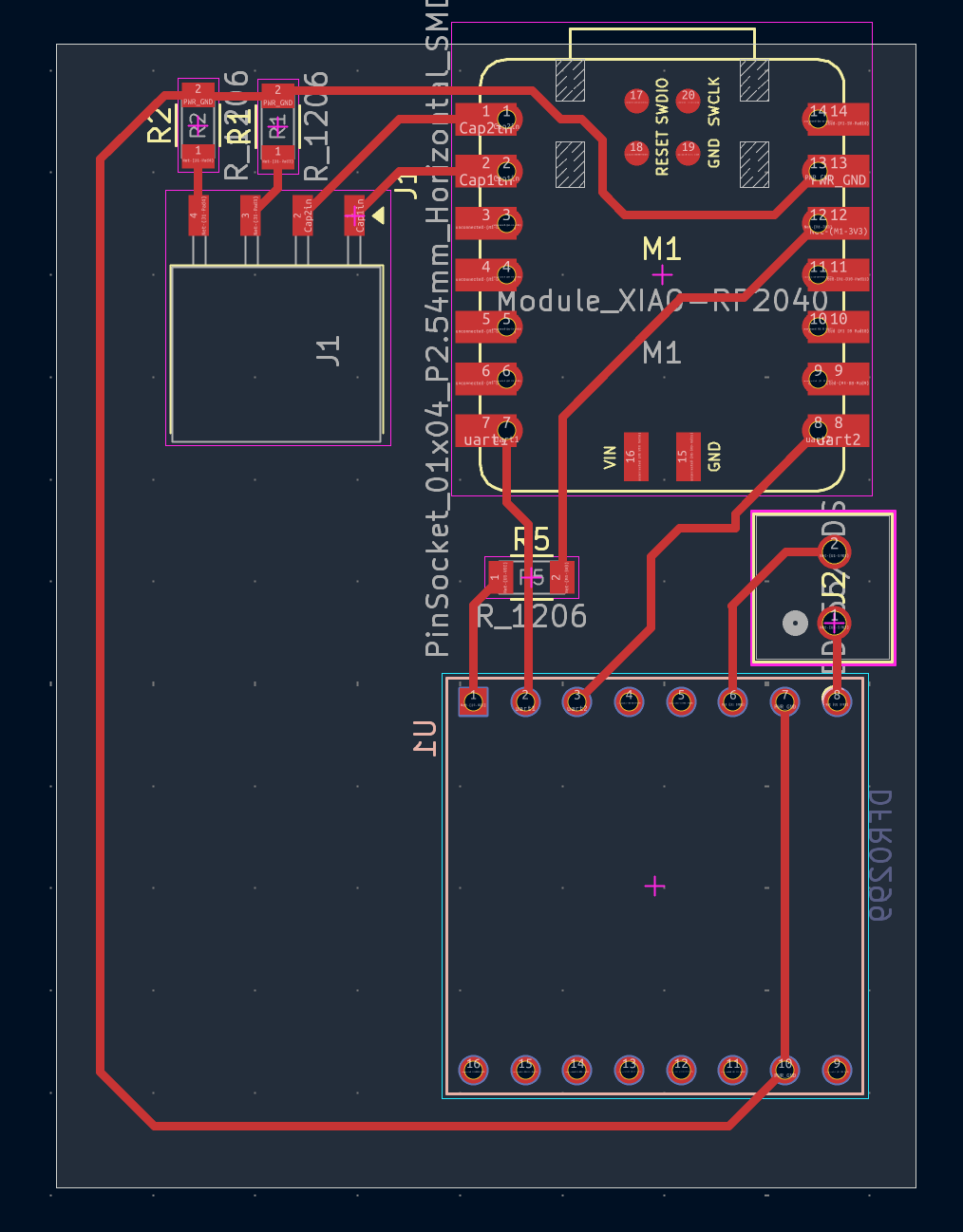
Notice that, in the current layout, the MP3 player would actually lay on the back of the circuit board.
It took me two failed attempts at milling this circuit board to finally have it behave the right way:
- Upon the first attempt, I forgot to include the drill file in the project, so I milled the circuit board without its holes. I thought that, not having detached the board yet from the bed, it would still be aligned in the correct position and I could just go ahead and drill the holes separately. While the holes were the correct size and relative position, they were misaligned with the rest of the pattern on the board. Interestingly enough, the vertical alignment seemed to be off by exactly one XIAO pin pitch. I wonder if this is a pure coincidence or some systematic error I made in setting up my milling jobs.
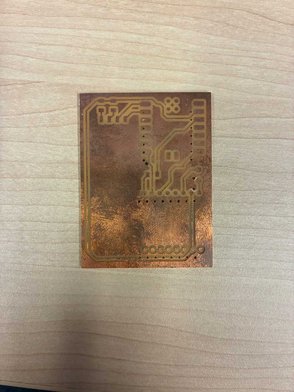
- The second attempt milled the board correctly but, when detaching the board from the bed, one of the traces close to the edge broke. I once again had to remill it.
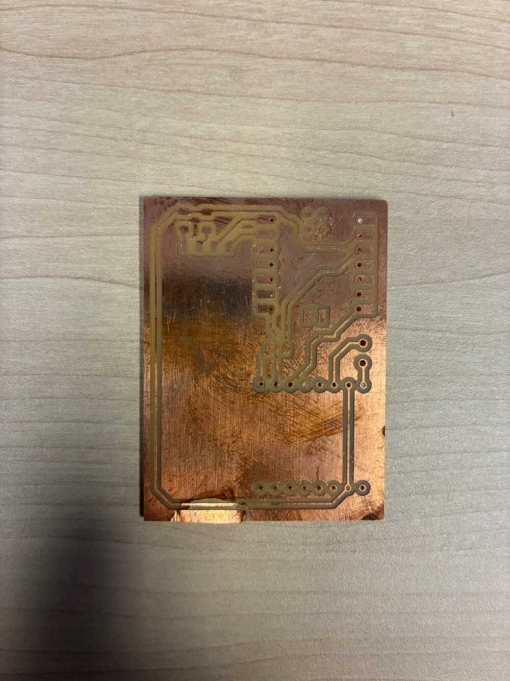
- The third milling attempt came out successfully!
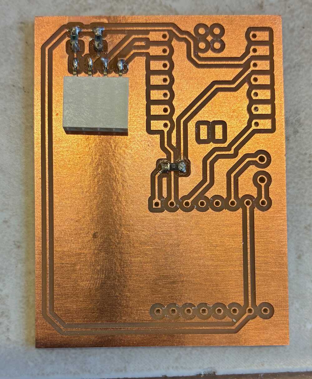
Soldering the board was relatively uneventful, except for the speaker. There was no way to attach it directly to the board and I had to use jumper wires. When trying to solder those, the corresponding PCB traces peeled off. Not wanting to mill another board, I soldered the speaker wires directly onto the MP3 player pins sticking out of the board, which turned out to work just as well, even if looking a bit sloppy.
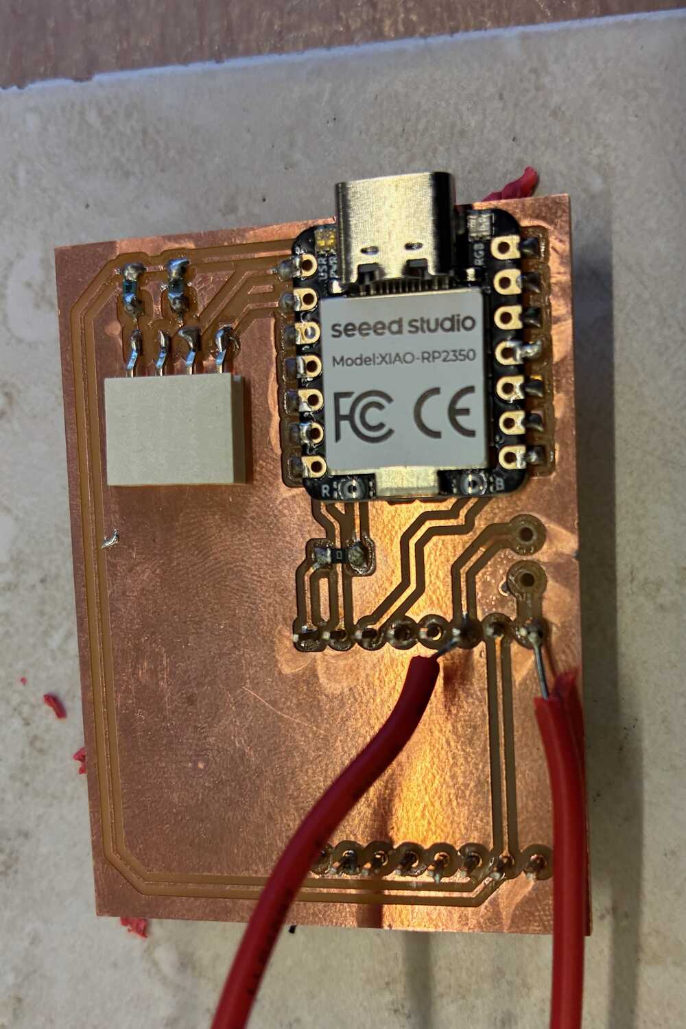
Finally, it was time to test my creation. Due to a lack of time on my end, I decided to simply test it using this code from the output devices week. Enjoy the Christmas music!