A $230 thermal-vacuum testbed
Update (week 4): I’ve switched my final project to a modular legged robot. I’m leaving this page up as my original week 1 work, along with the files that generated it. I’m returning the vacuum pot and magnets I bought for this version.
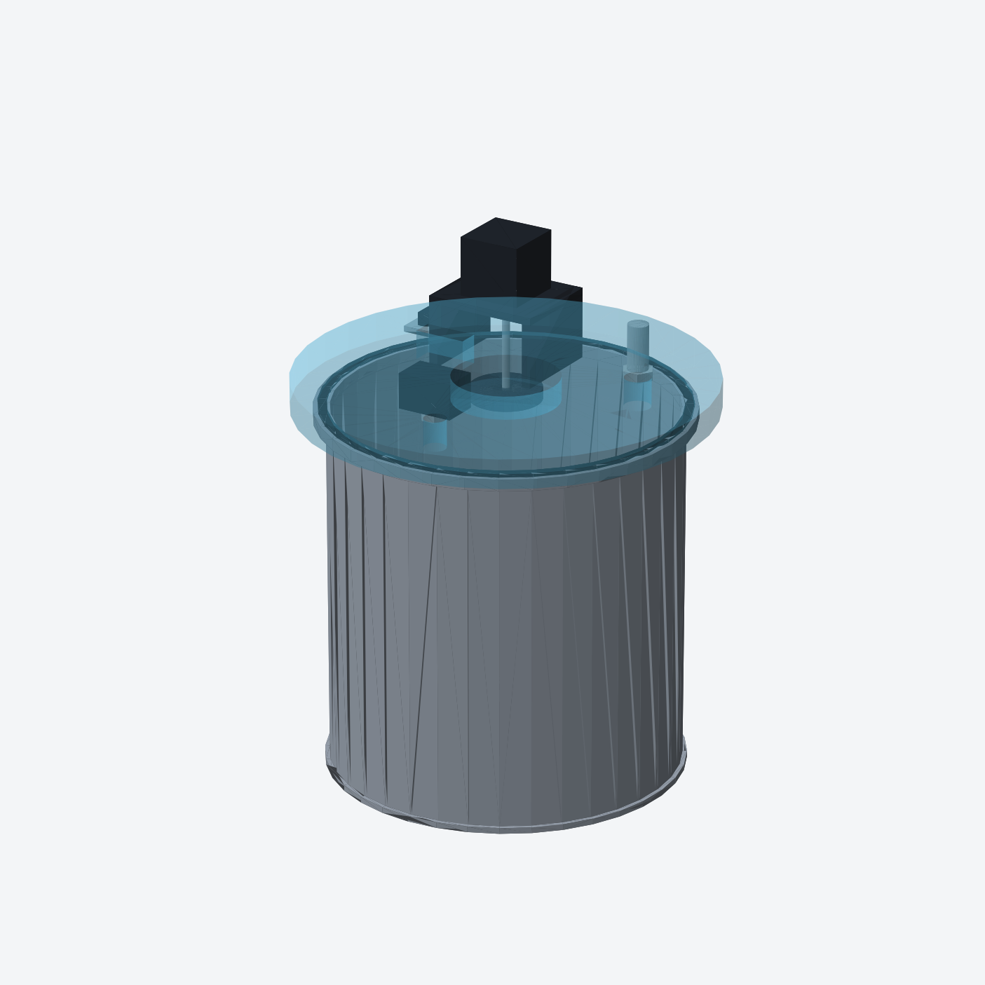
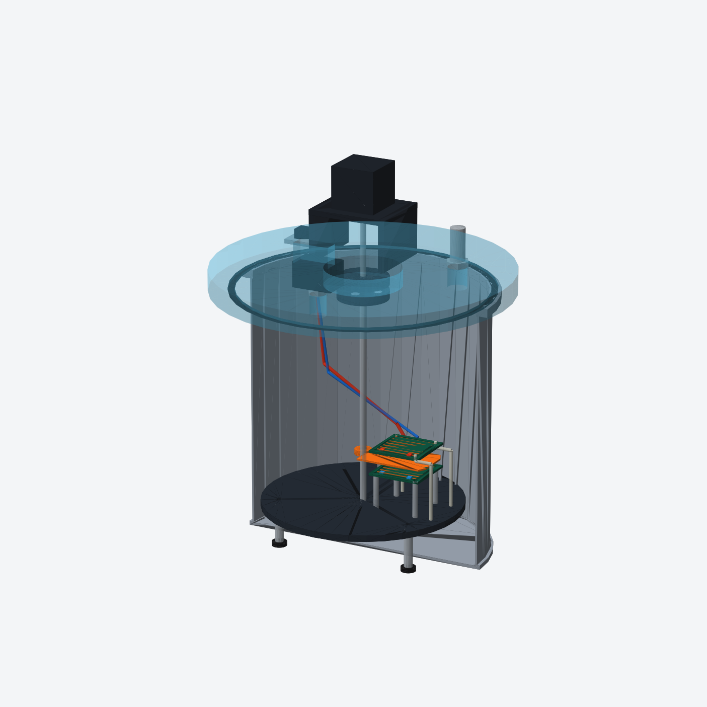
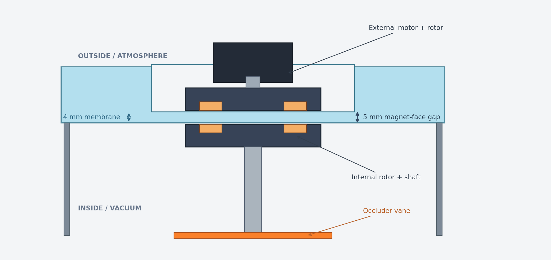
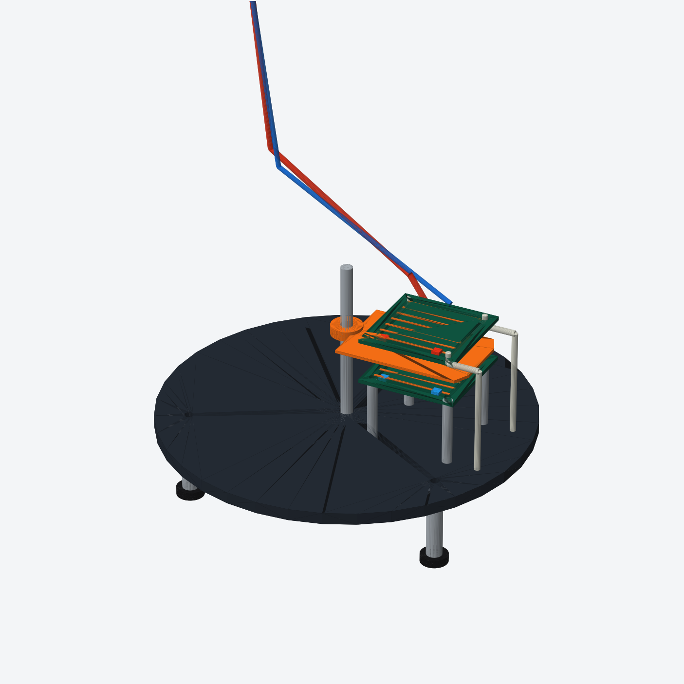
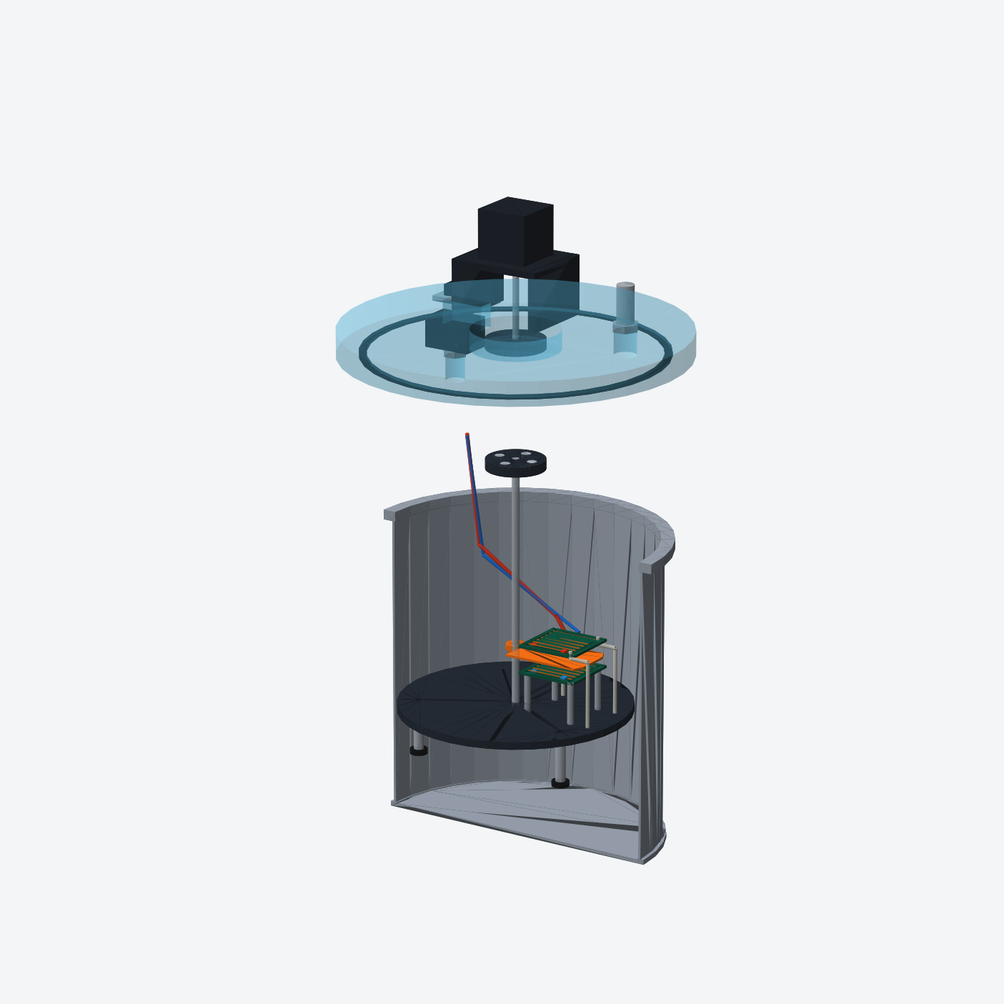
Part of my research looks at how groups of robots could survive a lunar night by huddling together to share heat. I'd mostly explored that in simulation, so my first final-project idea was to build a small thermal-vacuum experiment. I wanted to keep it affordable, starting with a stainless-steel vacuum pot rather than a custom chamber. The pot itself would stay as bought. I'd make an acrylic lid with the necessary ports, two 50 × 50 mm boards for heating and temperature measurements, a shutter between them, a rubber gasket and, eventually, a simple vacuum gauge. The shutter would be driven magnetically so I wouldn't need a rotating shaft seal through the chamber.
Physics first
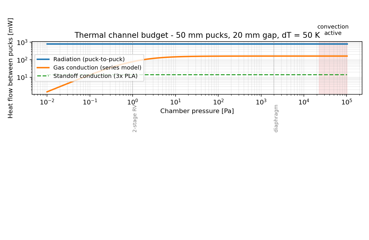
Before getting into CAD, I checked whether the experiment would be measurable with an inexpensive vacuum pump. In my model, the radiative heat transfer is about 0.8 W. There's also heat transfer through the remaining gas and the supports, but at the 10–50 Pa pressure range I'm targeting, those look small enough to account for. I'd still need measurements at different pressures and temperatures to separate the effects properly.
| Channel | Model | Result |
|---|---|---|
| Radiation, board to board | Parallel plates, effective emissivity 1/(1/ε₁ + 1/ε₂ − 1) | about 0.8 W, independent of pressure |
| Gas conduction | Series continuum + free-molecular, Λ = 1.2 W/m²/K/Pa | about 20% of signal at 2 kPa, 10% at 1 Pa, 2% at 0.1 Pa |
| Convection | Rayleigh number scales with p², off below Ra = 1708 | dies at roughly 20 kPa, so irrelevant under any pump |
| Mounting posts | 1D conduction through 3 posts, 3 mm × 15 mm | 14 mW (2%) if PLA in the budget script; 3 mW (0.4%) for the nylon posts the CAD script checks. Negligible either way |
Parametric CAD, with checks
I modelled the assembly in one parametric Python script, so changing a dimension also updates the parts and the checks. It calculates a 5 mm magnet gap, checks that the shutter doesn't hit the supports, and estimates heat conducted through the mounting posts at about 0.4% of the radiative signal. I went through five CAD versions. I originally considered a large acrylic tube, but the wall thickness needed for a comfortable safety margin pushed it beyond my budget. A metal pot looked like the more sensible starting point.

Reproduce it
The CAD and the thermal plot come from two Python scripts linked below. You'll need Python 3.11 or newer.
pip install "cadquery>=2.7" "numpy>=2.0" "matplotlib>=3.10"

python3 thermal_budget.py       # prints the budget table, writes thermal_budget.png
python3 testbed_pot_cad.py      # writes output/cad/*.step, output/cad/stl/*.stl,
                                # output/renders/*.png, parameters.json, design_checks.json
python3 testbed_pot_cad.py --cad-only       # skip the renders while iterating
python3 testbed_pot_cad.py --renders-only   # the opposite
The main dimensions are in the PARAMS dictionary at the top of testbed_pot_cad.py. The pot dimensions came from a product listing, so they would need to be checked against the actual pot before machining anything.
| Parameter | Value | What it is |
|---|---|---|
pot_inner_d / pot_height | 230 / 250 mm | the stainless stock pot, as listed |
lid_d / lid_t | 280 / 20 mm | cast acrylic lid; 20 mm so the port holes do not crack it |
gasket_mean_d, gasket_w, gasket_depth | 238, 6, 2.5 mm | cast silicone ring in a groove on the lid underside |
membrane_pocket_d / membrane_t | 72 / 4 mm | the thin spot the magnets couple through |
magnet_d / magnet_t | 8 / 3 mm | N52 discs, 4 per rotor, 5 mm face gap |
puck_size / puck_gap | 50 / 20 mm | the two heater boards and the distance between them |
occluder_swing_deg | 90 | shutter sweep; the script errors out if a post is inside it |
hot_support_post_d | 3 mm | three nylon posts, the parasitic path in the budget |
After changing a parameter, check output/cad/design_checks.json. It reports the magnet gap, possible shutter collisions and estimated heat conduction through the supports. I added those checks because they’re easier to forget when adjusting the model by hand.
Files
| testbed_pot_cad.py | the entire machine, parametric (CadQuery) |
| thermal_budget.py | the budget plot and table |
| parameters.json | the exact dimensions used for the renders |
| design_checks.json | the self-check output for those dimensions |
| requirements.txt | pinned Python dependencies |
| coupling_schematic.py | the simplified magnetic-coupling cross-section |