
A mobile robot that learns from contact
I am exploring a small indoor robot that can approach an obstacle, make gentle contact, and decide whether to push it or go around it. The project should make the relationship between hardware and behavior visible: wheel slip, compliance, sensor placement and a weak bracket should all have consequences I can measure.
My proposed starting point is a two-wheel differential-drive base with a rear caster and a replaceable front bumper. I would design the chassis, mounting parts, contact mechanism, wiring and embedded interface. Motors, bearings, power electronics and sensors would be purchased or drawn from confirmed stock.
Dimensions and performance targets are preliminary.
Explore the proposed hardware
Rotate the model, separate the layers, or select a part to see how I would make it. The model shows component packaging. The camera and force sensor are stretch modules.
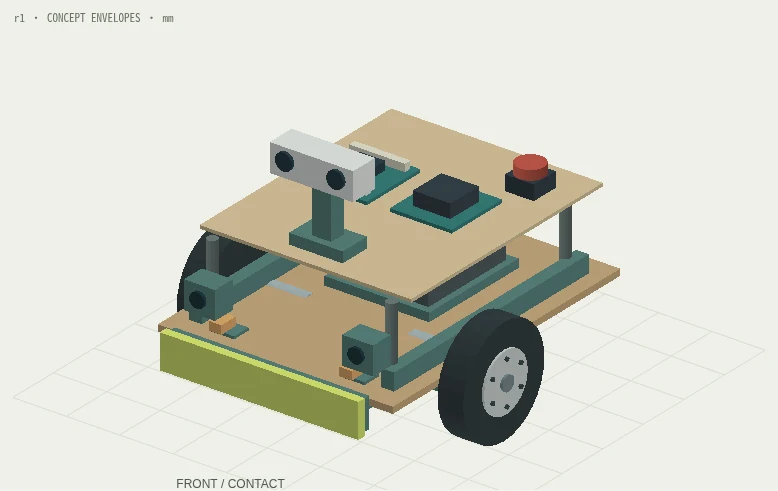
Loading the concept model. The drawing and fabrication table also work without JavaScript.
Explore the assembly
Select a part or a manufacturing process
Use the numbered component buttons to inspect hidden parts.
Concept envelopes only.
Download concept mesh (OBJ, mm) · Component data · Editable model generator.
What EECS shop can make
The shop can plausibly cover most of the custom structure, enclosures, contact parts and electronics assembly. Each process serves a particular part requirement.
| Machine / route | Robot parts | Boundary to confirm |
|---|---|---|
| CNC router | Lower 6 mm plywood chassis: contour, holes and cable slots. Start with a laser-cut cardboard fit model. | Avid observed in my September lab tour; the EDS public list names CNC Shark. Confirm the currently assigned machine, stock and tooling. |
| Universal laser cutter | Thin approved plywood service deck, cardboard packaging checks, drill templates and revision labels. | Material/thickness approval and kerf test first. |
| Prusa / Bambu FDM | PETG electronics tray, sensor mast, standoffs and prototype motor mounts. Separately print a TPU bumper pad with minimal supports. | Use the PLA/PETG and TPU lessons from Week 04. |
| Bridgeport + bandsaw | Optional aluminum motor brackets if printed clamps flex or creep. Saw approved stock, then machine reference faces and holes. | An upgrade if testing shows the printed mounts need more stiffness. |
| Electronics bench | Design an MCU carrier/sensor interface, assemble connectors, fuse/driver wiring and test sensors. | Soldering/microscope facilities are observed. PCB milling, reflow and fabrication routes are not confirmed. |
| Purchased components | Two encoder gearmotors, rubber wheels/hubs, caster, battery/charger, H-bridge, regulators and range sensors. Optional load cell and camera. | Select exact parts after torque/current and interface checks. |
Sources: my September 17 EDS lab photographs and subsequent printing work, plus the EDS equipment / Mobius listing (search listing checked September 30; full page was unavailable).
Three levels of ambition
1 / A reliable mobile base
Build the chassis, run two encoder speed loops, log supply voltage/current, and make a bumper switch stop the motor command. Demonstrate a repeatable straight run and turn with a reachable motor-power cut switch. Start with MCU control.
2 / Contact-aware behavior
Add short-range sensing and a guided bumper with measured travel. Approach a foam obstacle at a proposed 0.05 m/s contact speed, stop on contact, reverse and turn. Then add a load cell with mechanical overload stops and calibrate it before attempting a bounded push.
3 / Push or go around
Compare a movable foam block with a blocked one. Combine contact force, commanded motion and independent observation of displacement to decide when to stop pushing and take a detour. An optional camera adds object tracking; encoders alone cannot distinguish motion from wheel slip.
The hardware reasoning I want to demonstrate
Drive torque, traction and speed
A 100 mm wheel needs about 48 rpm at 0.25 m/s. For an initial sizing exercise, assume a 2.5 kg robot, 0.3 m/s² acceleration, a 5° slope and rolling-resistance coefficient 0.03:
F = m × [a + g sin(5°) + 0.03 g cos(5°)] ≈ 3.62 N
T per wheel = F × 0.05 / 2 ≈ 0.091 N·m
With a 2 N contact load: T per wheel ≈ 0.141 N·m
With a 2× design allowance: about 0.28 N·m per wheel
This is required wheel-output torque at the operating point, not motor-shaft torque or a stall-torque target. I would select the gearbox and motor from their speed/torque/current behavior, then test heating. Gearbox losses matter when converting to motor-shaft demand; this simple estimate also omits wheel inertia and turn-scrub losses. Pololu’s motor guidance warns that stalls can damage motors rapidly, so a large advertised stall torque is not a continuous rating.
If 70% of the weight is on the driven wheels and friction is 0.5, the simple traction limit is about 8.6 N. I need a pull/traction test on the actual floor; more motor torque will not fix a slipping tire.
Load paths and print orientation
Drive forces should pass through clamped motor brackets, rails and the chassis, not thin printed tabs. I would start with PETG fit parts and through-bolts, then measure wheel-axis deflection before deciding whether metal brackets are worth the additional machining. The broken PLA connector taught me to consider wall count, orientation and load alongside material choice.
Stability and serviceability
The two drive-wheel contacts and rear caster define the support triangle. Place the battery low, keep the loaded center of mass inside that triangle, and check braking and bumper loads rather than just static balance. The service deck comes off independently of the drive mounts. Wires get strain relief and clearance from wheels.
Compliance, sensing and calibration
A removable TPU pad spreads contact over the front bumper; a guided rigid backplate defines the motion and sensing direction. Travel stops bypass the load cell under overload. Start with a switch, then calibrate force versus load and check hysteresis after assembly. The TPU support-removal problem motivates a separate flat-printable pad mechanically captured by the rigid part.
Power and control
Fused logic branch → regulated supply → MCU + sensors
Encoders / bumper → MCU → speed loop + watchdog + driver enable
Optional host → bounded velocity request → MCU
Route noisy motor power separately from signal wiring while maintaining the required common electrical reference. Verify current limits, wiring, fuse and driver ratings together. A watchdog stops commands when the host disappears. The motor-power switch removes drive power but does not guarantee braking distance or stop all stored motion.
A planning example of 36 Wh nominal energy, 70% usable allowance and 20 W average load gives about 1.26 h. The first measured runtime target is 30 minutes; the camera/computer budget comes later.
Tests that make the understanding visible
| Question | Proposed experiment | Record |
|---|---|---|
| Do the wheels track evenly? | Repeat a 1 m straight run and a 90° turn, five times each. | Endpoint and heading error; encoder traces; effective wheel radius and track calibration. |
| Is the structure stiff enough? | Apply a known static load at the bumper and motor mounts, with drive power disconnected. | Load/deflection and residual deformation; inspect fasteners and printed layer direction. |
| Does contact stop the base? | Approach a foam target at 0.05 m/s under supervision. | Detection latency, travel after contact and repeatability; aim for no more than 10 mm additional travel, subject to testing. |
| Is pushing different from slipping? | Compare movable and blocked foam objects with independent displacement observation. | Force, wheel motion, actual object motion and decision outcome. Proposed 2 N push limit only after calibration. |
| Does the electrical system stay stable? | Log start/turn transients and a 30-minute run. | Voltage sag, resets, current and temperature versus component ratings. |
Measurements, failed attempts and revisions will be added here as the project develops.
What I can realistically own
The first deliverable can be a custom chassis, designed mounts and bumper, my own embedded interface board and firmware, plus documented integration with bought drivetrain and power parts. I can explain why a feature is routed, laser-cut, printed or purchased, and show the test that justified a revision.
Exact purchases remain open: two motors and encoders, two wheels/hubs, one caster, a matched protected pack/charger, one dual driver, regulators, switches, connectors and two range sensors. The load cell/amplifier and camera/host are optional. Confirm shop access, materials and the course budget before committing to the BOM.