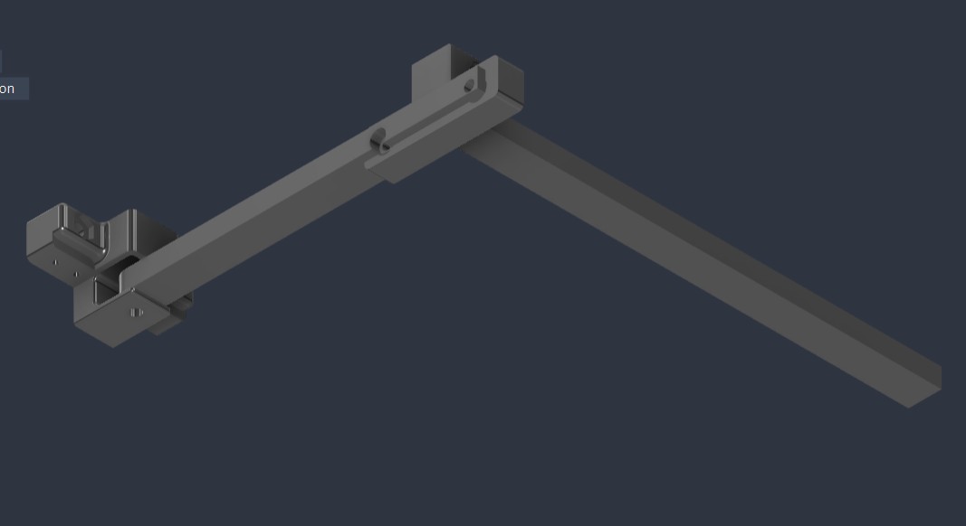
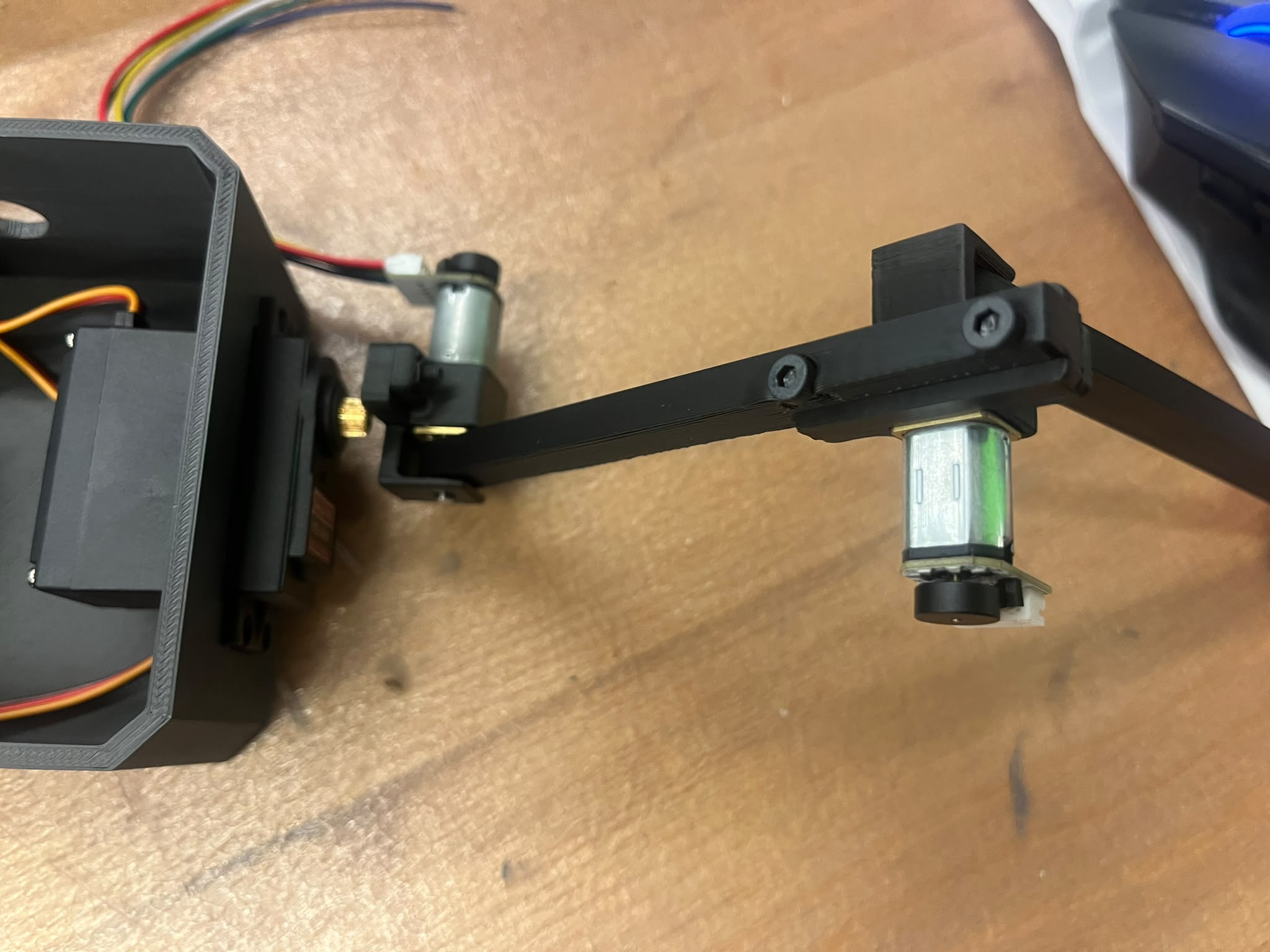
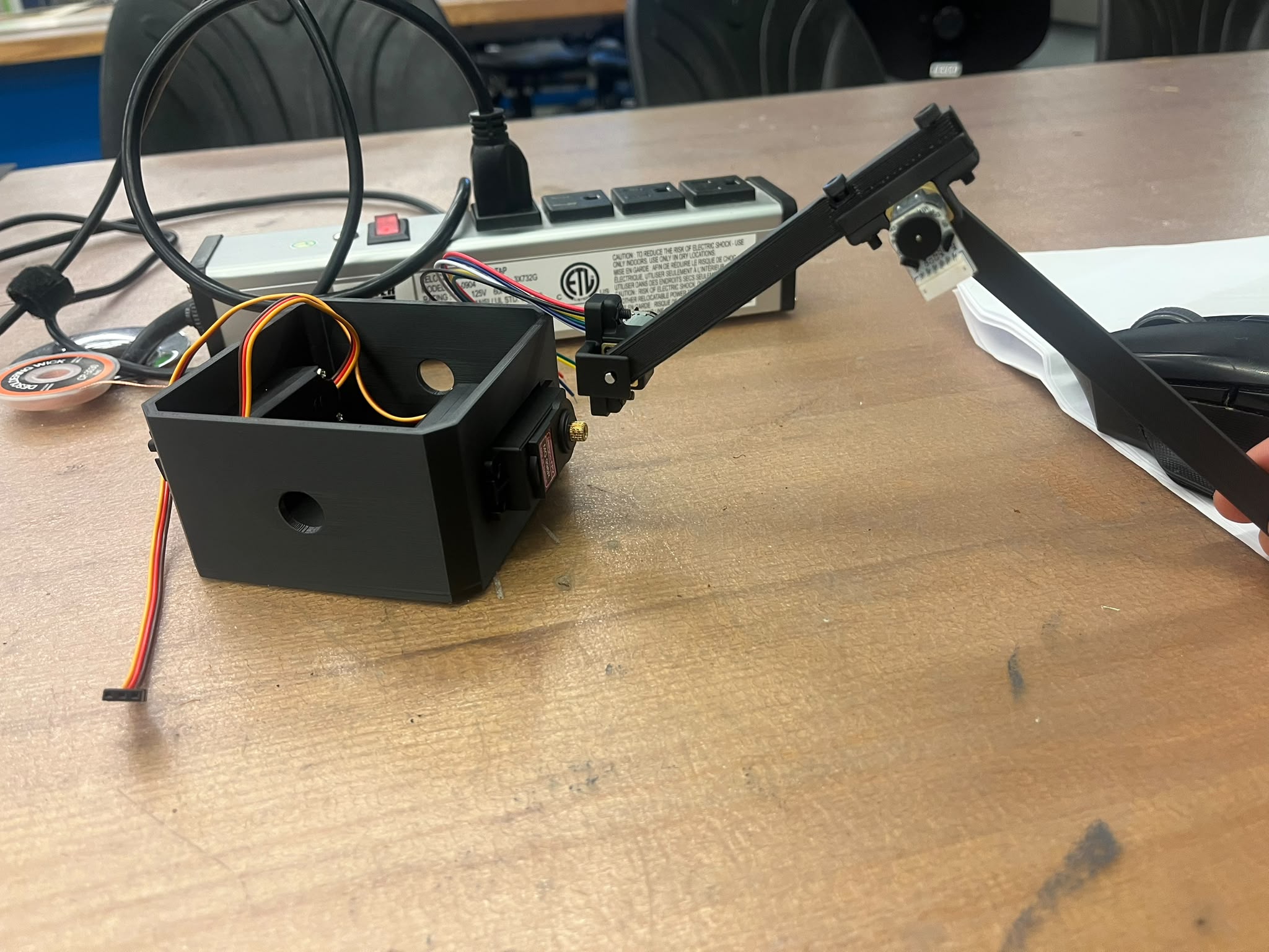
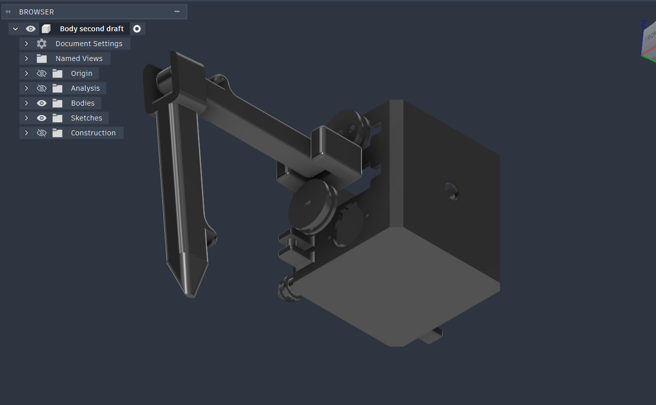
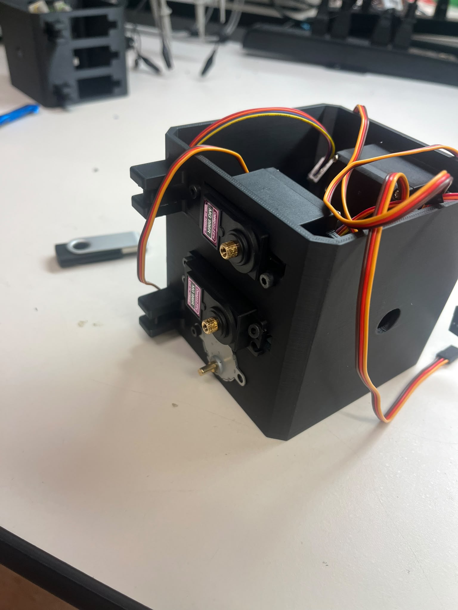
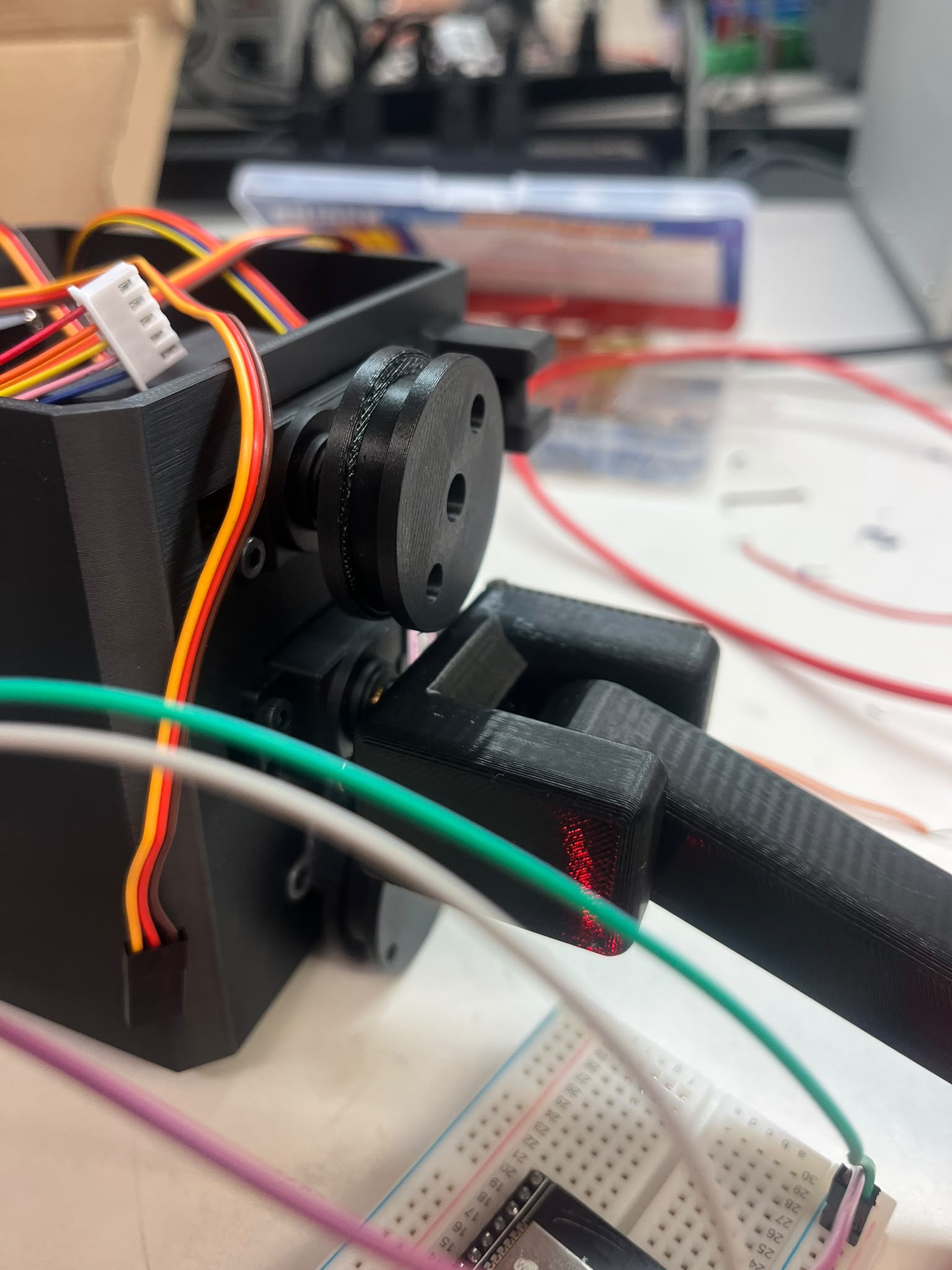
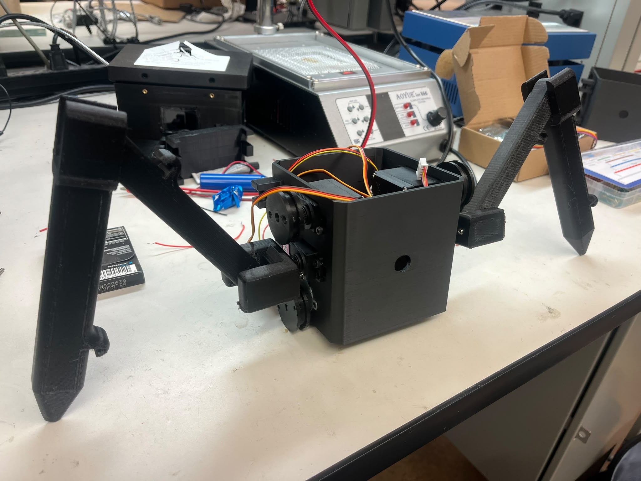
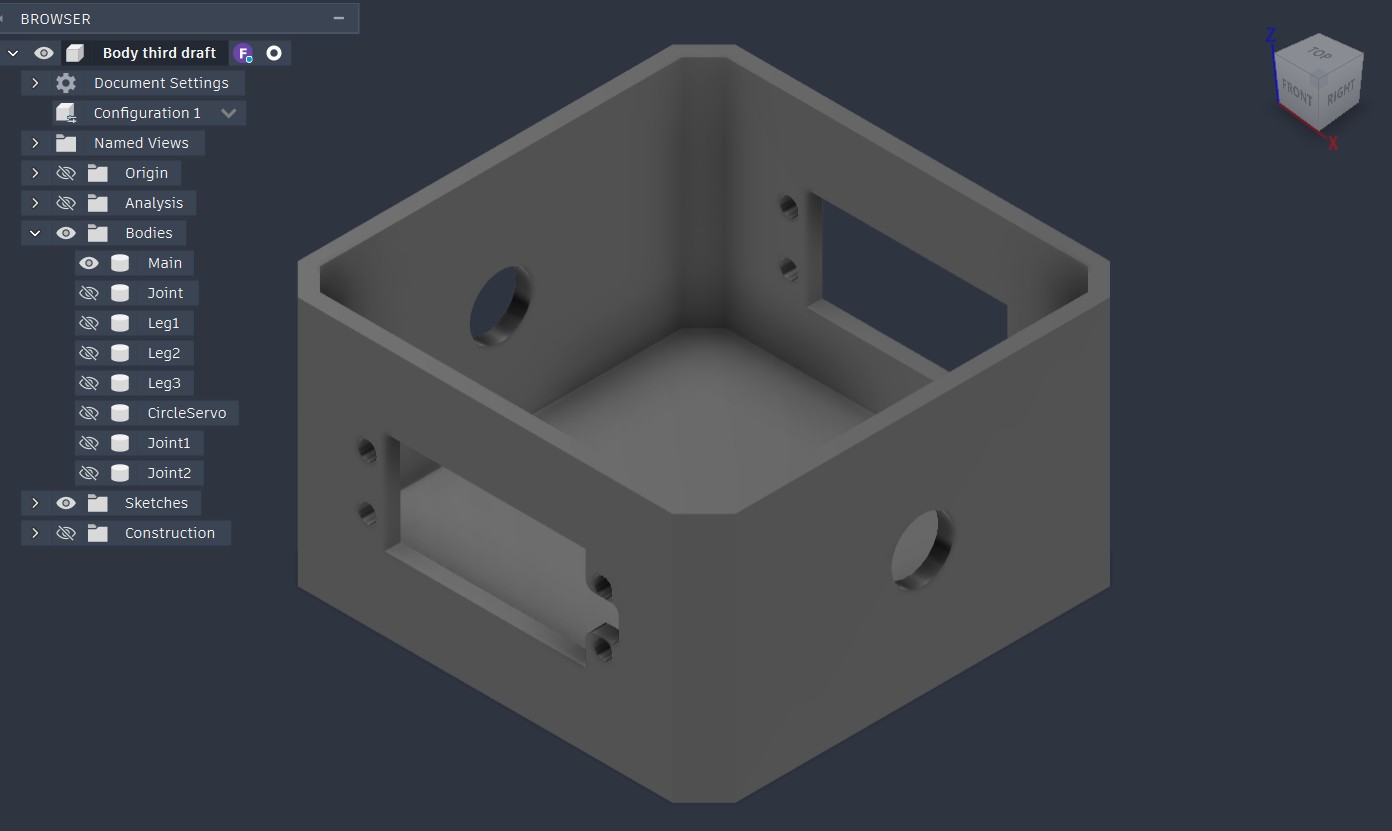
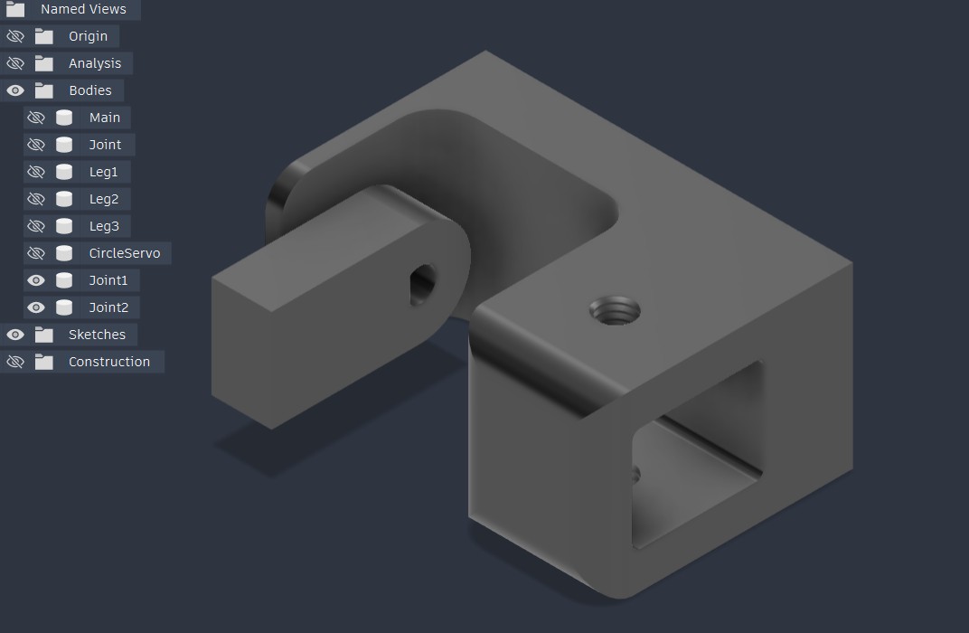
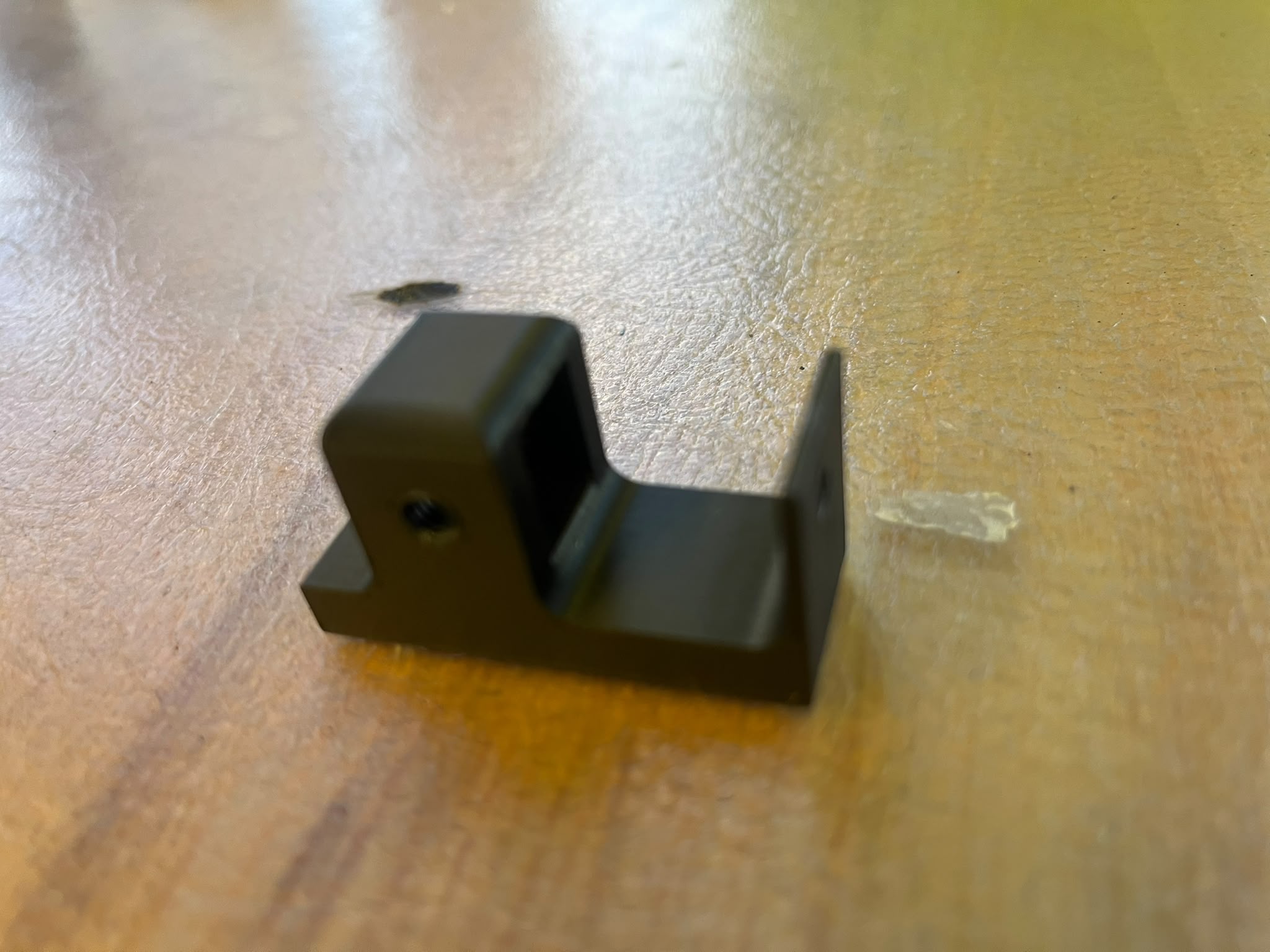
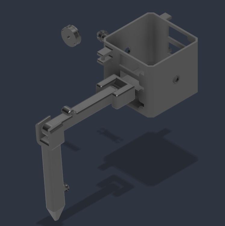
This week I've been working on the rework for the robot's legs. I have to mount the micro motors on the joints of the robot's legs, and directly couple the the legs together via the motor's shaft. I continued working on the cad from last week and came out with this.
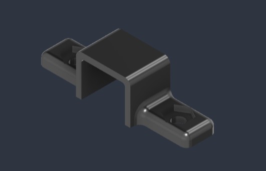
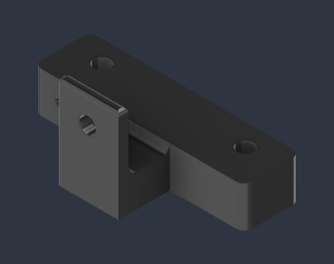
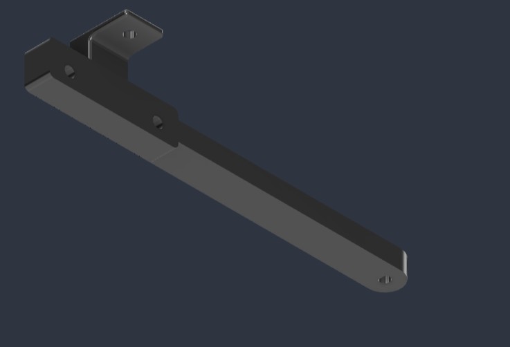
There are four relevant pieces:
The first is a "clamp" that goes on top of the dc motor and holds it in place through an M3 screw.
The second is the base that attaches to the main body via the servo attachment. The aformentioned piece goes on top of it, and the motor's shaft is kept in place by the small slot.
The third piece has a slot for the motor's shaft, and is the upper leg. It has a spot at the end to fit another motor and connect to the lower leg.
The fourth piece is more simple and just has the attachment to fit on the motor's shaft. Based on observations from inital trials, I will modify the part that comes into contact with the ground. I will also add some high friction surface to the tip, such as griptape or rubber.
After a couple iterations of 3D printing to get the tolerances right, I assembled the system and installed the motors. These legs are significantly skinnier than the past iteration, which is good because it reduces the weight of the entire system. The main body is also significantly lighter, although the servos are still considerably heavy.
To experiment with the motors, figure out how they work, and how the encoders work, I wrote some basic C++ on Arduino IDE to read the encoder's output. The video below shows me powering the motors with 12V from a power supply and sending the encoder's data to an ESP32. I personally counted the rotations per minute to make sure that my data was correct
Week 4
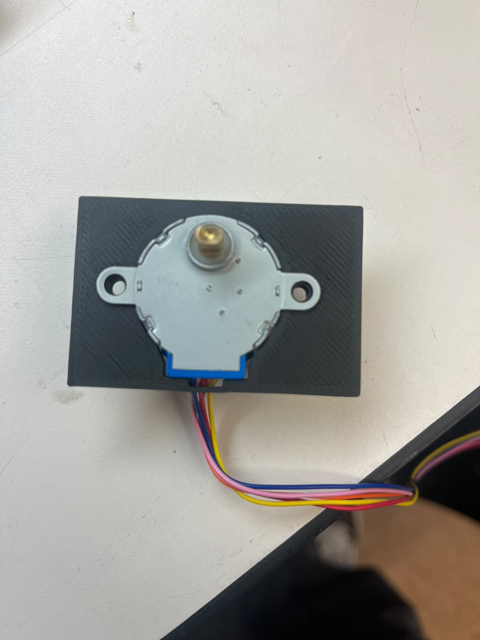
For this week, I wanted to start assembly. I got this servo from amazon, as stated from last week's progress. I also realized that the lower leg couldn't be fully extended with just the 180 degrees available from the servo (the rotational movement of 180 degrees could not be translated into enough linear movement to move the leg as far as it should go). So, I also bought these stepper motors. The idea behind this choice was that the stepper motor is capable of moving its shaft by a precise amount. I then swapped the hole on the bottom of the sides to be a spot for the stepper motor, rather than the servo.
To avoid wasting a lot of pla in getting the offset right for the fit for the servo, I printed a thin rectangular prism with the hole embedded. I was able to iterate through different offsets quite quickly, and settle on a nice snug fit.
With these parameters in mind, I printed the entire body, and my project was ready for initial assembly. I drilled some holes into the box to fasten the servos and steppers to the main body
I then screwed the legs to the linear servo attachment so that it fits right on the middle servo. I also connected the circular servo attachment to the circular piece.
The assembled module looks like this.
For prototyping, I ran the system with 5V from a power supply, and connected the servos and steppers to an esp32. I wrote a simple program that moves the servo back and forth for testing, and after some debugging with the connections in the circuit, was able to achieve this movement:
While this looked promising, I had an important realization...
THIS IS NOT GOING TO WORK
For starters, the stepper motor I have is ridiculously weak; it cannot provide nearly enough torque to move the leg. To be honest, I don't know how this motor is expected to move anything beyond a piece of tape.
Secondly, I realized that my plan to use wire to push and pull the leg also isn't going to work. Wires aren't good for pushing anything at all, so unless I rigged a spring to the joints to pry them open (which is very difficult and unreliable), there's no way wire would work.
Lastly, the module was getting too heavy. Four servos and two steppers made the main module too heavy for me to confidently estimate that the legs can actually support the body, especially considering how this doesn't include the weight of the battery I will eventually install.
Major FP Rework:
After careful consideration, I decided to embed small motors into the joints of the leg instead of diverting the task to the main body. This is a design tradeoff where I chose to add weight to the legs (instead of the main module) in exchange for reliability, simplicity, and a significantly reduced module weight. This also allows me to greatly reduce the size of the main module (from 4x4x4 to 3.5x3.5x2) I found this motor suitable for my needs. It is very small, high torque (1:1000 gear ratio with 2.5 kgf.cm of torque), with an included encoder for high precision movements.
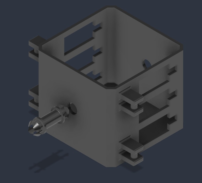
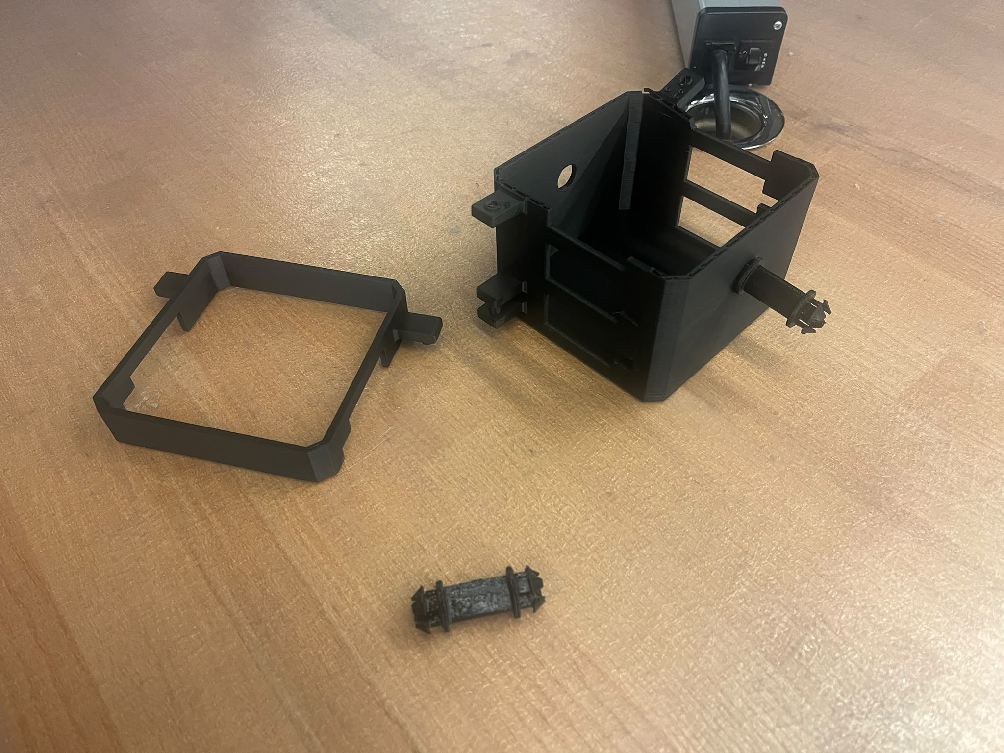
The new main module now looks like this, with added screwholes for ease of installation.
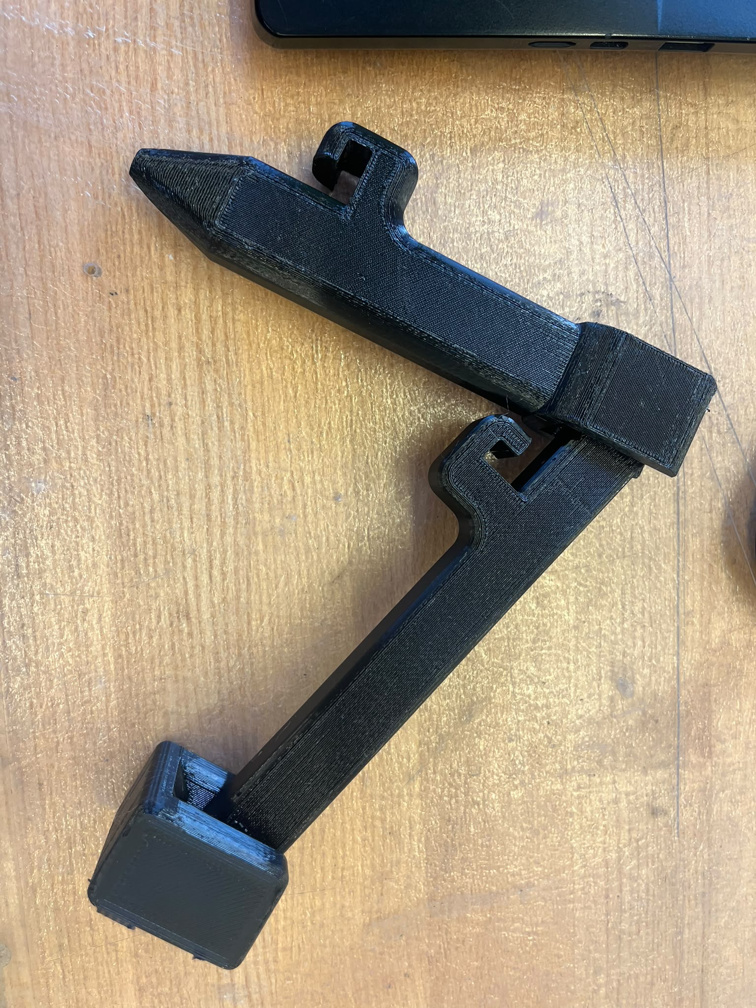
I also need a new leg piece, which will not be printed in place, since I need to insert the new motor. The new piece shown below is supposed to fit the small motor in place, and has threaded screw holes on the sides to pinch the motor in place (Size M4).
The first iteration of the main body came out fine, and the new leg piece required approximately four iterations to get the fit and constraints just right.
Week 3
For the embedded programming week, I would like to get the main motors for my system working and decide on the mechanisms that will be used for movement. For ease of reference until I decide on a final name, the robot will be called LED.
I want each walking leg to operate with three joints:
One joint at the base of the bot that swivels the leg forward and backward
One joint near the base of the bot that moves the leg up and down, allowing the robot to raise and lower its body
One joint near the middle of the leg that functions as a "knee," allowing the leg to extend and retract
For the first joint, I plan on using this servo. By attaching it directly to the base of the robot, I should be able to integrate it into the body relatively easily once I model the system in CAD. I chose this servo because it appears to offer a good balance between torque, weight, and cost. Although the servo is heavier than the smaller 9 g and 12 g servos that are available online, its 55 g weight provides significantly more torque, at around 12 kg/cm, compared with the roughly 1–2 kg/cm available from many inexpensive micro servos. I think the additional weight is worthwhile for the additional torque available at the base of the leg.
For the second and third joints, I have several potential design ideas:
Mount two additional servos directly onto each leg. This would be the simplest approach mechanically and would minimize the amount of mechanical linkage required between the actuator and the joint. The main disadvantage is that it would add a significant amount of weight to each leg. This is especially problematic for the joint farther from the body, since the base joints would then have to lift and move the weight of the other motors.
Use linear actuators on the legs. This could allow the joints to remain relatively compact while producing a more direct pushing or pulling motion. However, the actuators may be heavier and more expensive than servos, and the range of motion would have to be carefully designed. Depending on the geometry, the motion could also become less efficient near certain positions.
Use strings or cables to actuate the joints. Instead of putting every motor on the leg, motors could remain closer to the robot's body and pull cables connected to the joints. This would significantly reduce the weight of the legs. However, cable stretch, friction, and slack could make the system less precise and more difficult to control.
To start, I will implement the third method, using bicycle brake cable to maintain tension and control how much each leg folds.
Firstly, I designed the body of the robot, which would house the servo's, electronics, etc. and a joint to connect distinct modules of the main body. My initial design (picture not shown) had just one slot for the servo, and a longer joint. After printing them, I noticed I needed a greater offset for the servo to fit, and could make the body smaller, and the joint shorter. The cylinder shaped protrusion is designed so that any wire can be passed through it onto the actual leg, creating a sort of pulley system. Whether it actually works, I have no idea.
Fail:
The first time printing the model shown above, it cracked at one of the seams created from the servo shaped hole. However, the connector piece would work and snap right into place with a little bit of leeway.
I then designed the leg joint, which is intended to print in place, facilitating the final assebly. The two hooks shown are intended to tie off the wire used to push/pull the legs. I Also designed the circular piece shown on the left to translate circular motion from the servo to linear motion onto the legs.
The first leg joint print ended up looking like this. The joints would move back and forth as intended, but the middle leg joint ended up feeling a lot longer than it should have, and the hooks are larger than they need to be. I took an inch off the first leg joint, and added an inch to the second leg joint, and reduced the hook size.
Week 2
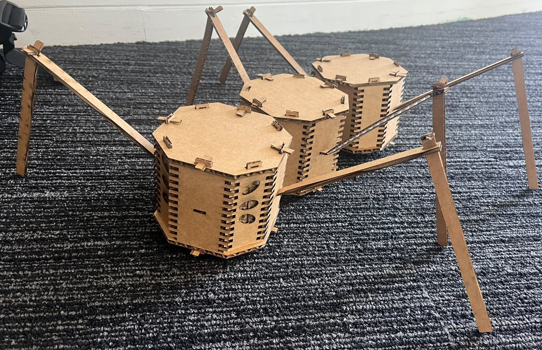
My lasercut ragdoll is intended to show what my final project is intended to look like. It helps me identify the exact scale and size I would like for my final project. Details on the construction can be found here.
Week 1
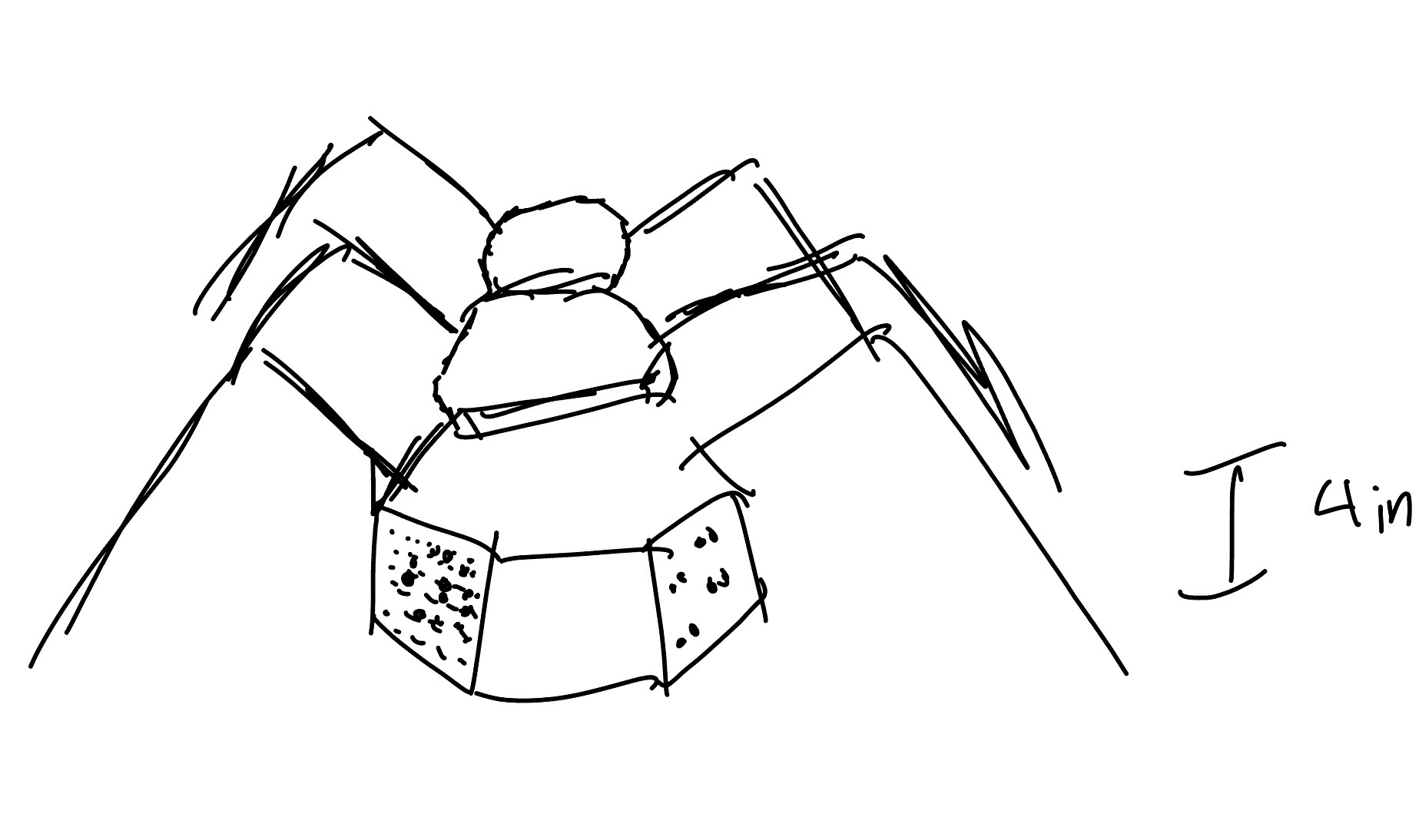
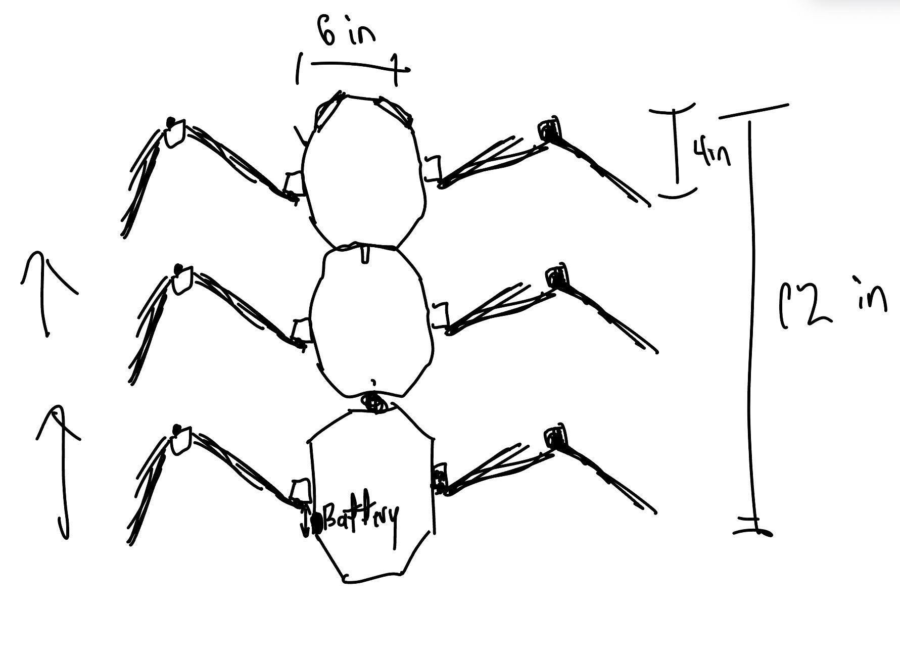
Some mockups for the initial design of my final project, with ideas for the initial scale.