Week 6 — Electronics Production
This week I have designed and fabricated the testing PCB for my vacuum tube silicon-free Geiger counter.
PCB Design
Since the PCB I designed last week was already ordered, I had to design a new PCB for this week. I was thinking of something fitting for the retro aesthetic a milled PCB has: a vacuum tube Geiger counter. The idea is to make a silicon-free Geiger counter, running purely on vacuum tubes, such that in case of a nuclear explosion, the electromagnetic pulse (EMP) would not destroy the device.
The problem in this case is generating the high voltage from batteries using vacuum tubes. My plan is to first build a simple blocking oscillator circuit, which will produce low duty cycle pulses, and then feed those pulses to a step-up transformer generating the high voltage. With the help of Claude, YouTube, and some old design manuals for tube blocking oscillators, I designed the following circuit.
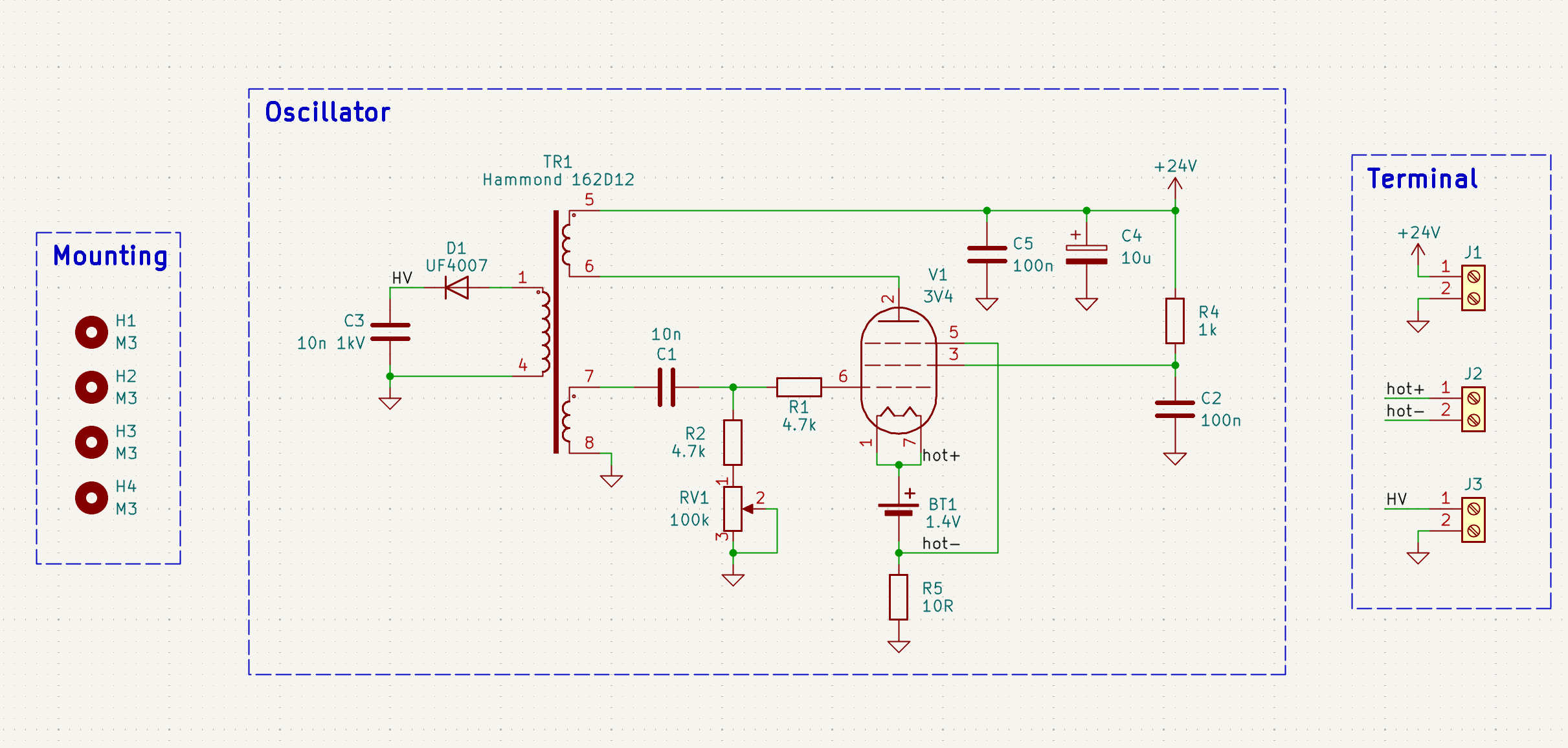
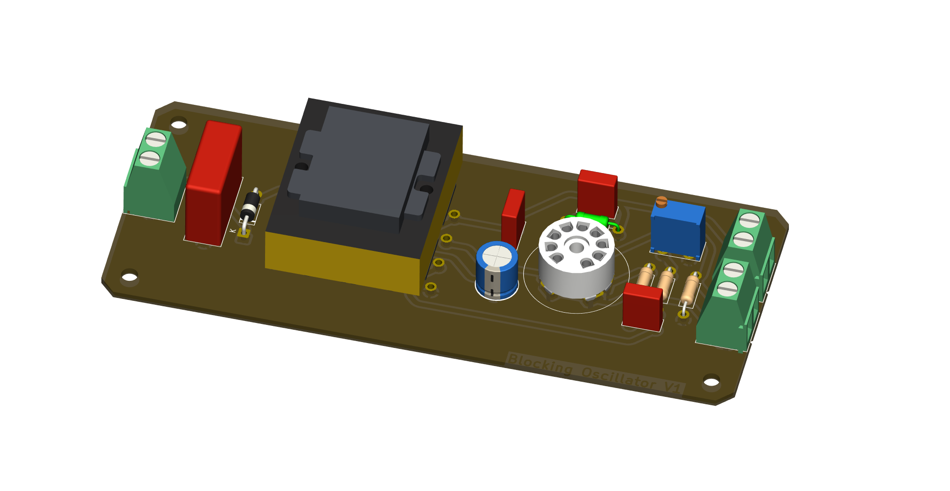
As vacuum tube and transformer footprints are pretty difficult to find online, I designed all the footprints, as well as symbols, myself. The models in the 3D render are just approximate; I have tried to match their dimensions with the real parts; however, modelling them from scratch would take way too much time, so I used models that seemed close enough.
Generating the Toolpath
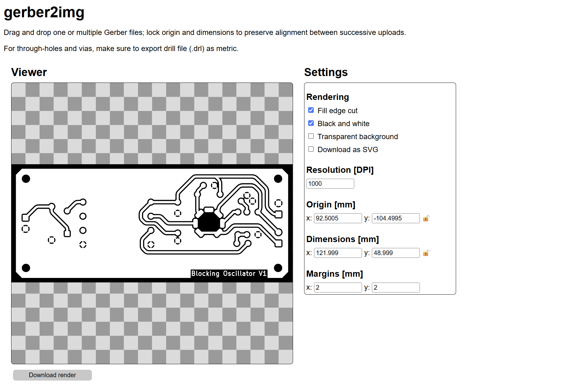
To generate the toolpath, I used a tool provided by our TAs. It was important to place the edge cuts and the drill files in the same render, as that operation uses the 0.8mm drill bit. The copper layers need to be rendered separately, as they use a different end mill on the carvera. Below are the settings I used for the Gerber-to-PNG conversion.
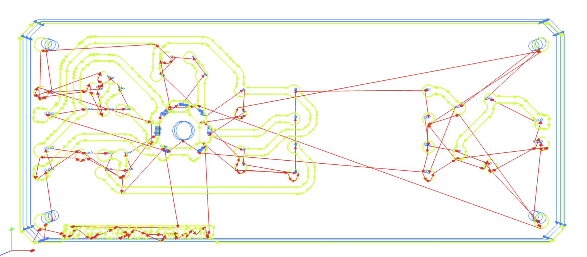
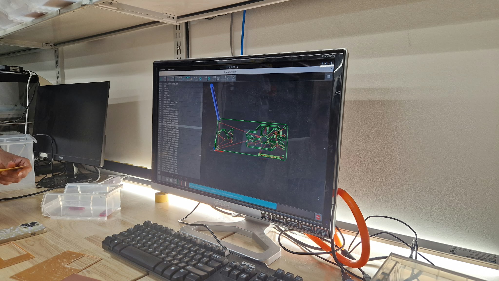
A tool path generated by the modsproject script provided to us by our TAs. It was important to see if the green lines are present in the image; if not, the traces will not be cut.
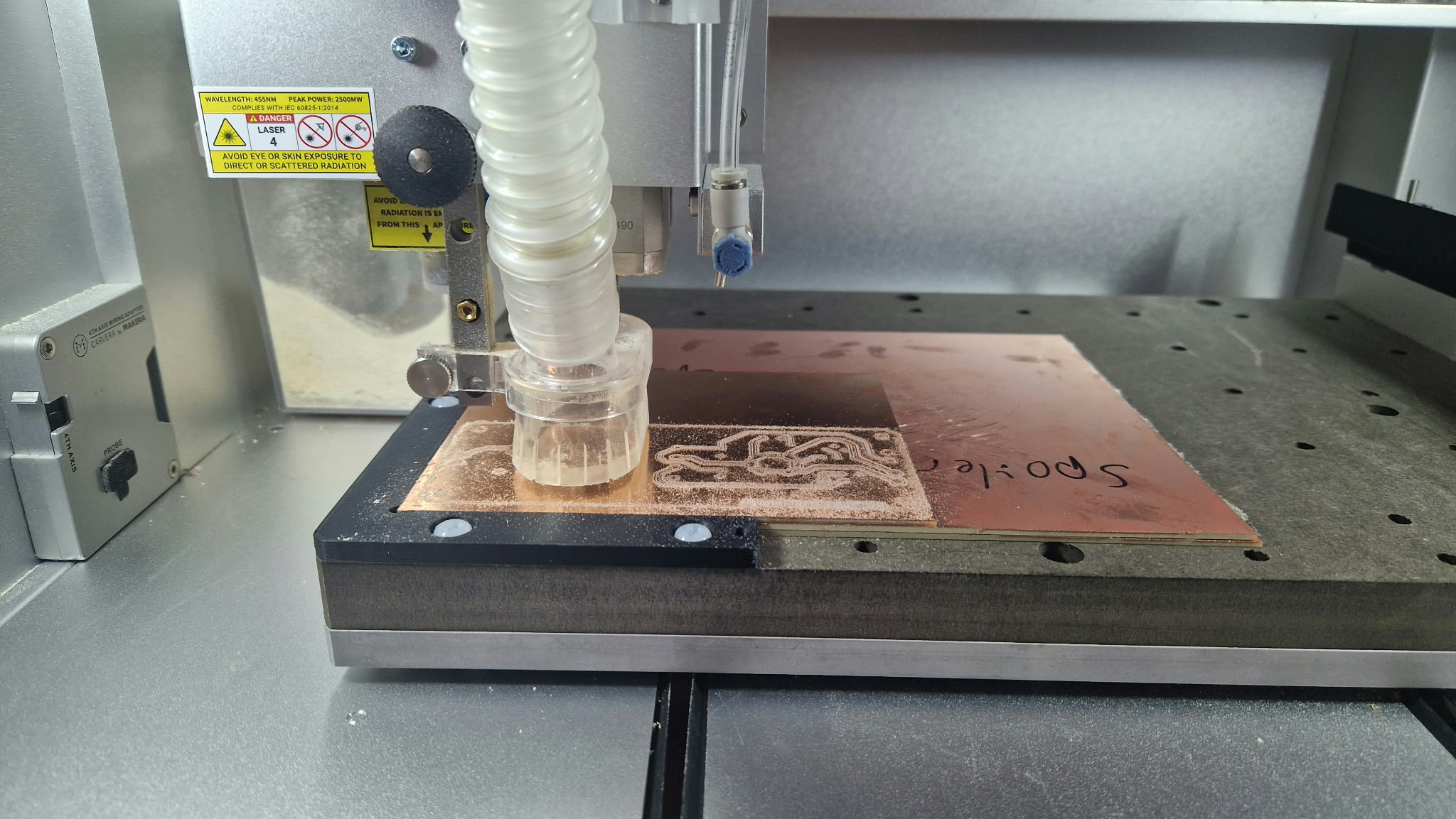
The FR1 PCB was secured using double-sided tape onto the buildplate of the Carvera. Then the origin offset was set to at least 1mm from either edge of the tool aligner tool. The image below shows the G-code progress of the machine in real time.
The Results
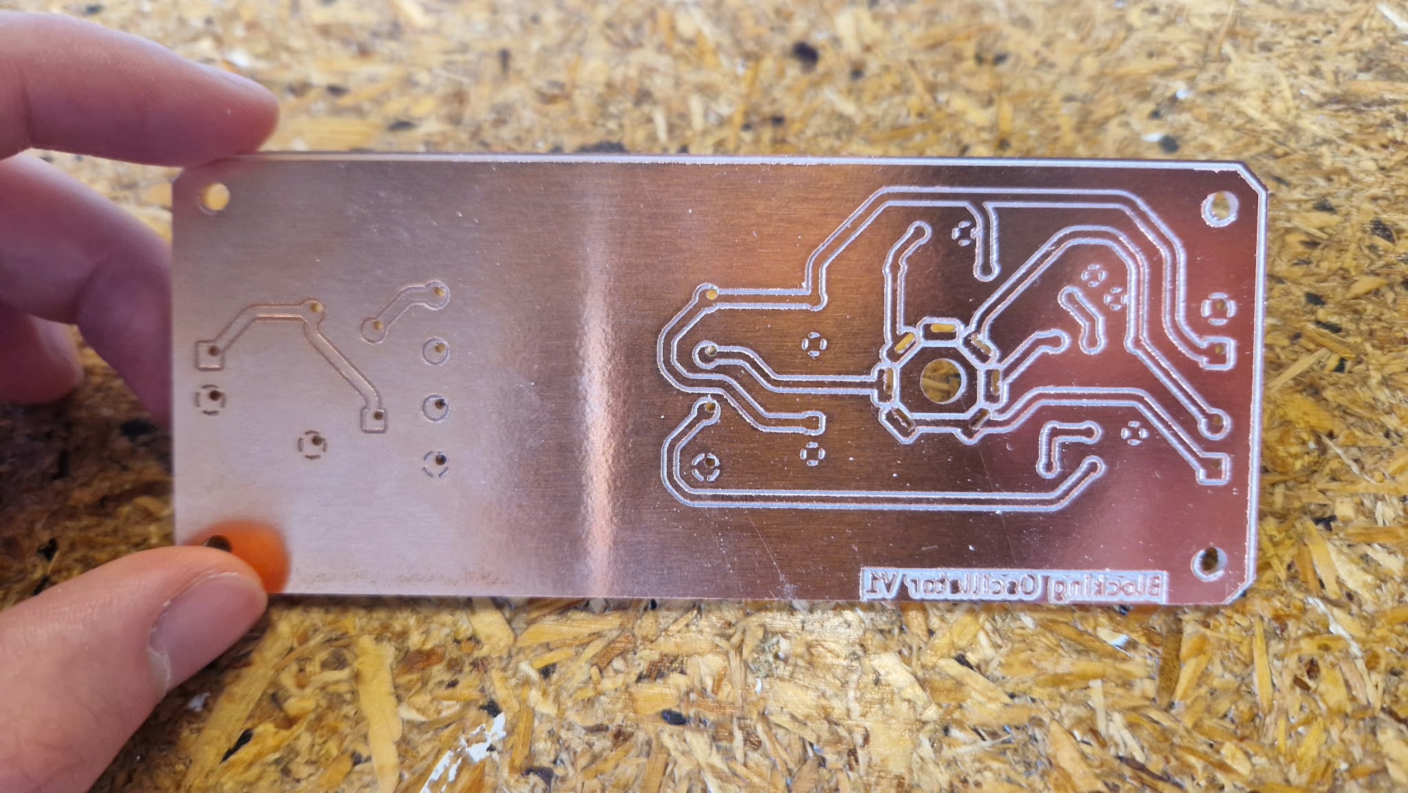
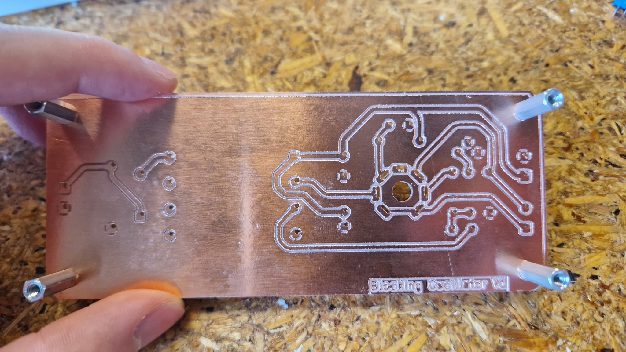
The first PCB turned out quite well; however, some of the smaller holes did not get cut. When I checked this in KiCad, the omitted holes were 0.8mm in diameter, which was the exact size of the cutting mill. It is still a mystery to me why this happened in the first place, but after making the holes with 1.1mm drills and a 2.2mm pad diameter, the holes were able to be milled correctly. The first image shows the bad PCB with the missing holes; the second image shows the PCB with every hole milled correctly.
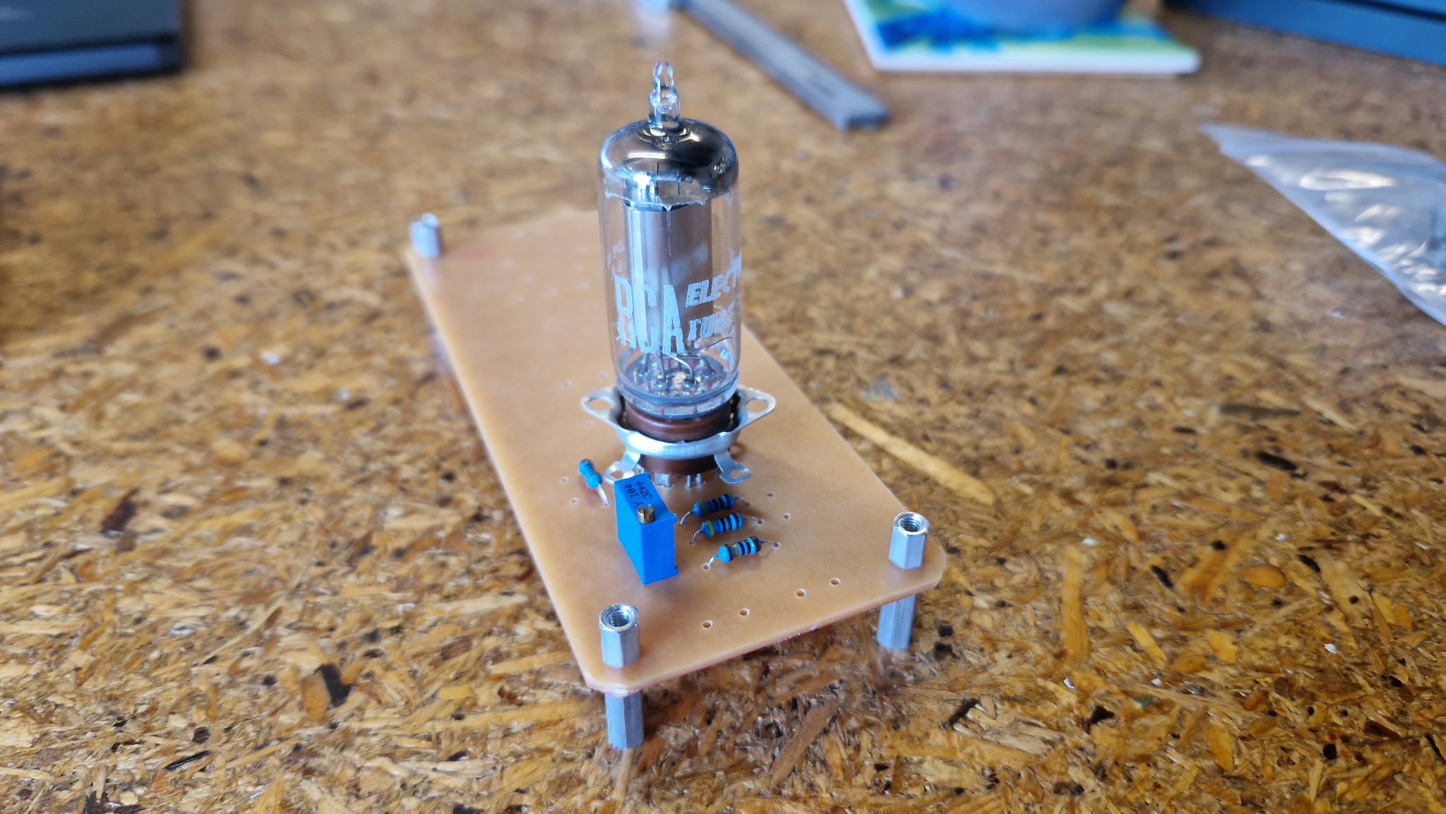
This is the final PCB with the miniature 7-pin vacuum tube socket and the 3V4 (pentode) vacuum tube itself. As of now, I am still waiting for most of the components, so I could not assemble the whole circuit yet. Unfortunately, a lot of the vacuum tube circuits require manual fine-tuning of the component values, so it's still quite difficult for me to make a tube circuit work straight off the schematic. I did not want to solder the components directly, as I will likely be changing the component values in the process of making the circuit oscillate.