Final project: programmable droplets
Xiangtao Shi | HTMAA 2026
Idea
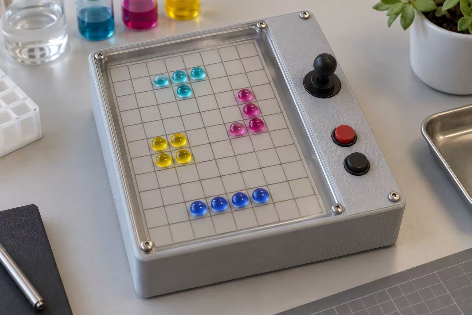
My first-week proposal was a Tetris-inspired game made with programmable liquid droplets. The idea started with Microfluidic Bubble Logic and the Tetris game on MIT's Green Building. I wanted to try making a game where the pixels could move and change shape.
I will start with two neighboring electrodes, then try a loop around the outer eight cells. The size can change and a larger game board or a DIY display will come later.
Discussion with Neil
Neil suggested this task is very non-trivial. The reason is two folds. First is the surface treatment, which means the surface should be hydrophobic enough so that the droplet doesn't wet the surface (sharp contact angle). Second is the voltage. It may need a strong electric field or voltage to control the droplet, which might be dangerous. But he said it's a nice goal and that would be a really interesting challenge. He was interested in whether this could become a way for Fab Labs to make their own DIY displays using electrowetting.
He pointed me toward Volta Labs, OpenDrop, and The Electrowetting Display video. He also offered to introduce a Volta Labs founder if either progress or get stuck.
Reading notes
These are the papers and project resources I have read after the discussion.
- OpenDrop: An Integrated Do-It-Yourself Platform for Personal Use of Biochips, Alistar and Gaudenz, 2017. They try to make digital microfluidic chip easy to fabrication and accessible to every users, so they come out several ways by changing the materials and lowering the cost. I focused on the PCB electrode array and the surface-treatment experiments. The droplet needs enough contact area to reach the neighboring electrode. The paper describes thin-film approaches using Saran wrap, Parafilm, or ETFE, with different surface treatments.
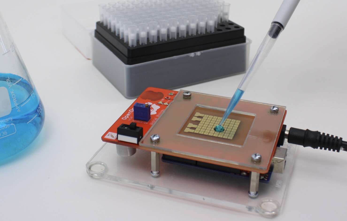
OpenDrop prototype. Reproduced from Mirela Alistar and Urs Gaudenz, Figure 1, Bioengineering 4(2), 45 (2017). doi:10.3390/bioengineering4020045. - Electrowetting Displays, Feenstra and Hayes, 2009. Figure 3 helped me understand the oil/water pixel: applying voltage moves the oil aside and exposes the underlying surface. The voltage discussion explains why dielectric thickness matters. I cannot assume the same voltage will work with my materials.
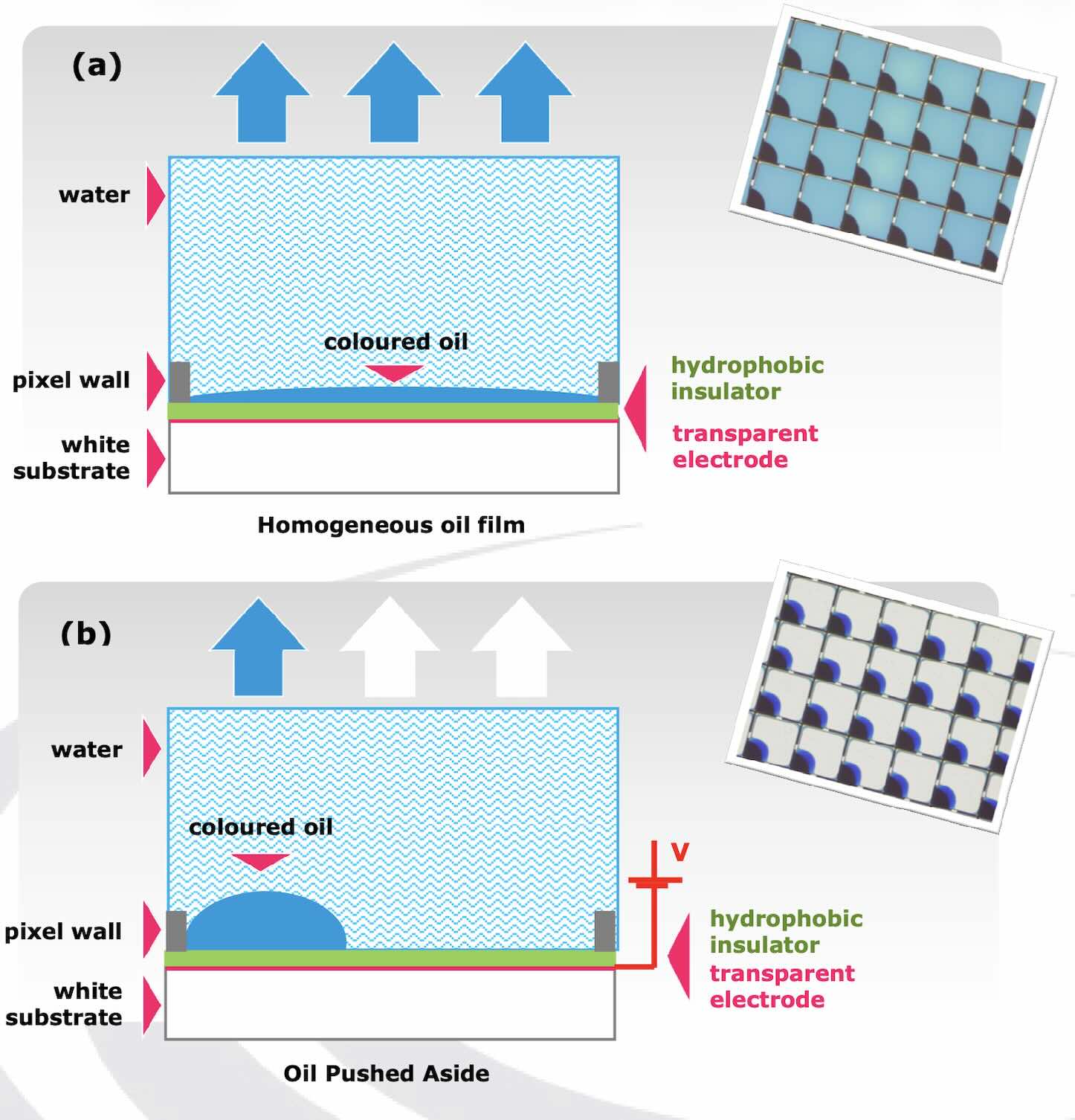
Electrowetting pixel structure and switching. Source: Johan Feenstra and Rob Hayes, Electrowetting Displays, Figure 3, May 2009. How the parameters affect voltage
The Young-Lippmann relation connects the contact-angle change to voltage:
For a fixed target contact-angle change, rearranging it gives:
Here Δcosθ = cosθ(V) − cosθ(0). Holding the target response and other parameters fixed:
Parameter Effect on required |V| Dielectric thickness d A thinner layer lowers voltage: |V| ∝ √d. Relative permittivity εᵣ A higher value lowers voltage: |V| ∝ 1/√εᵣ. Interfacial tension γ A lower value lowers voltage: |V| ∝ √γ. The voltage-reduction discussion (section 4.4.3, p. 10) considers both oil-film and fluoropolymer thickness reduction.
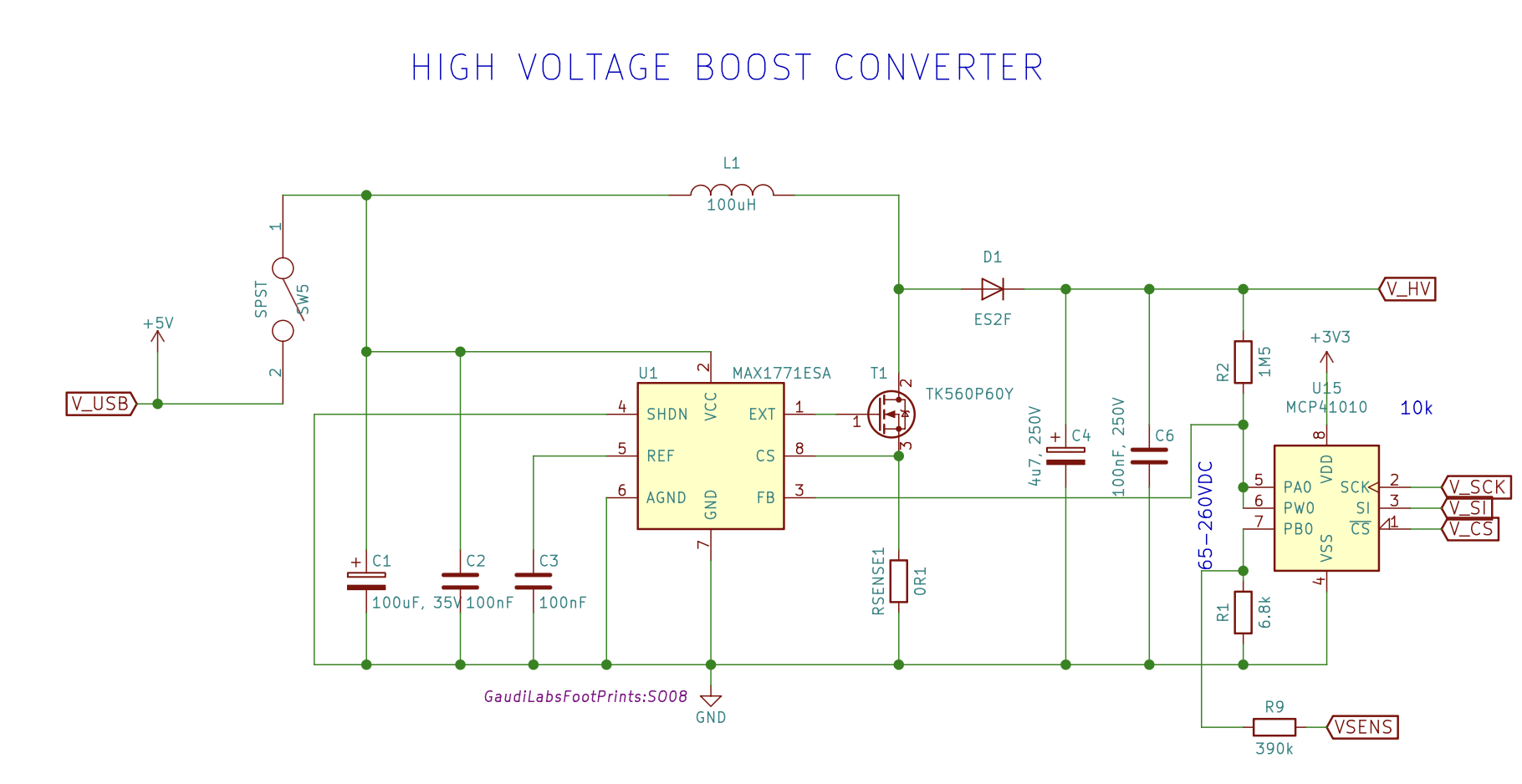
- OpenDrop design files and cartridge fabrication notes. In my first draft, I want to use the local V3/V3.2 electronics as my high-voltage reference. The MAX1771 circuit generates the high-voltage supply, the MCP41010 participates in voltage adjustment, and the HV507 chips switch the electrode outputs.
- A full description of a simple and scalable fabrication process for electrowetting displays, Zhou et al., 2009, is a reference for choosing materials and understanding pixel fabrication.
- DropletIO is a reference for using programmable droplets as an interface.
Saran wrap and Parafilm are available in my lab and my home, so they are candidates for the first material tests. I also considered the lab's PFOCTS coating process in another project.
Electronics design
I have drawn the low-voltage controller schematic and design its PCB in KiCad. It uses a XIAO RP2040, an I²C OLED connector, a start/stop button, two 10 kΩ resistors, and a 100 nF decoupling capacitor. The board will be powered through the XIAO's USB connection.
J2 is a custom low-voltage control connector for the future high-voltage board. It carries data, clock, latch, blanking, polarity, AC selection, the digital-potentiometer chip select, and a planned HV_RUN enable signal. This board does not generate high voltage.
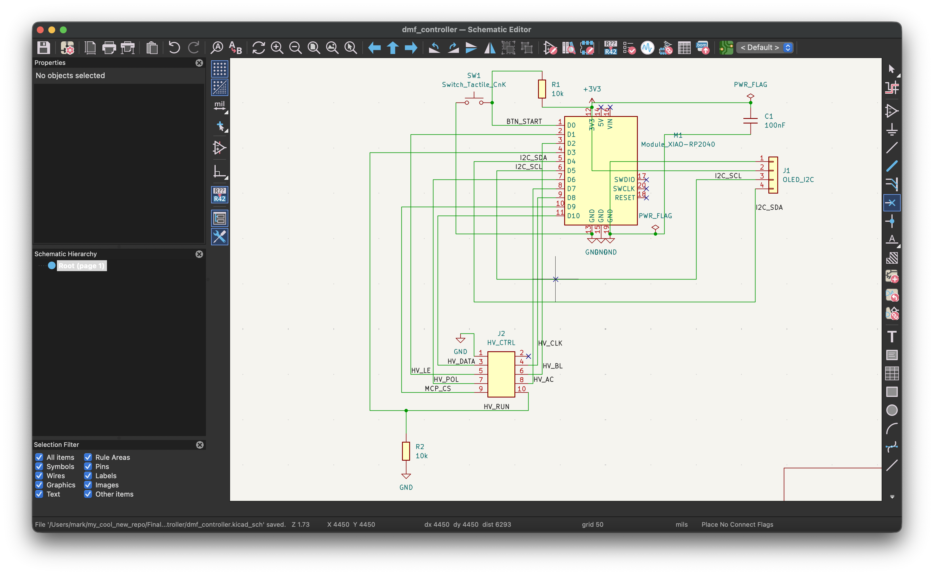
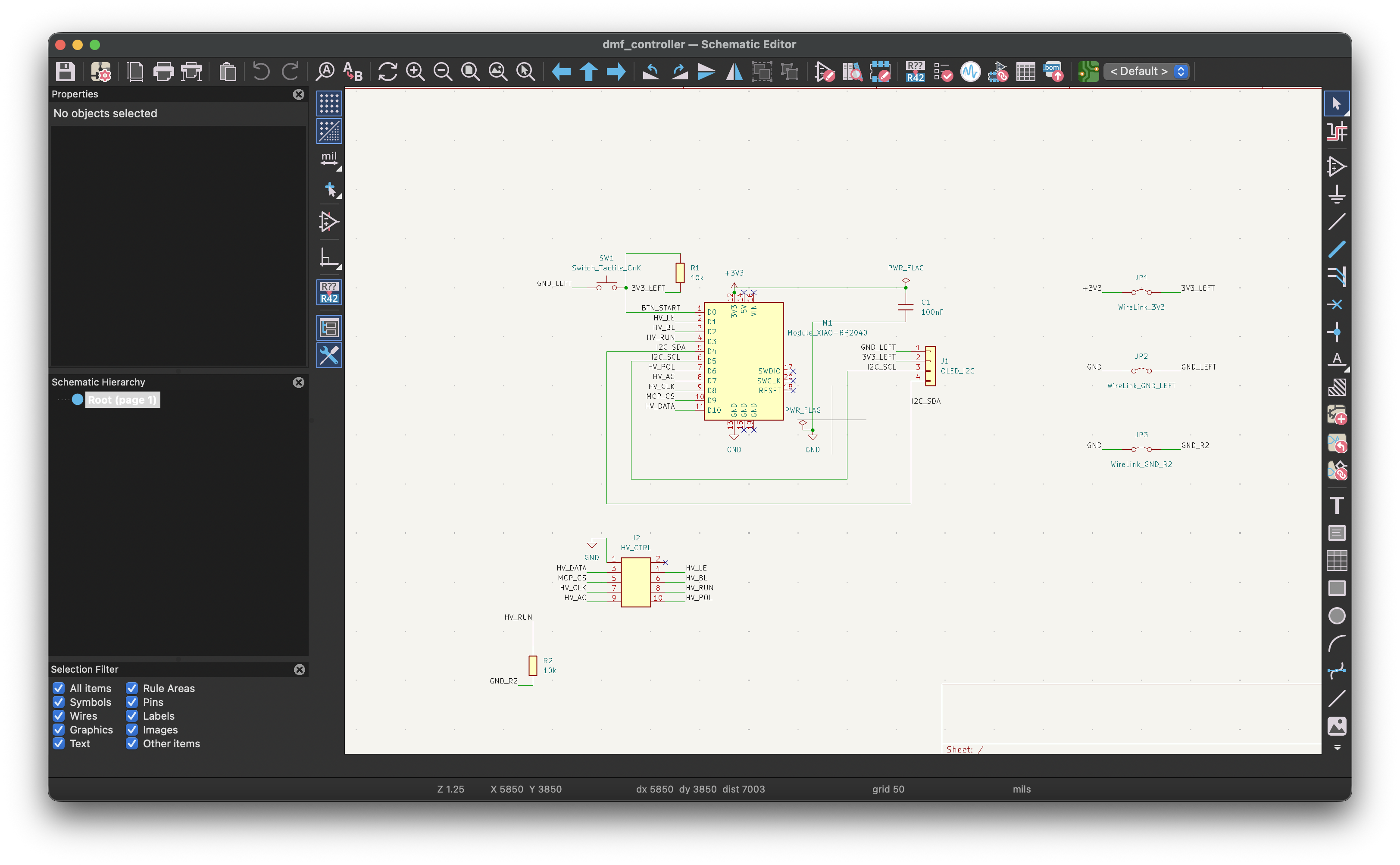
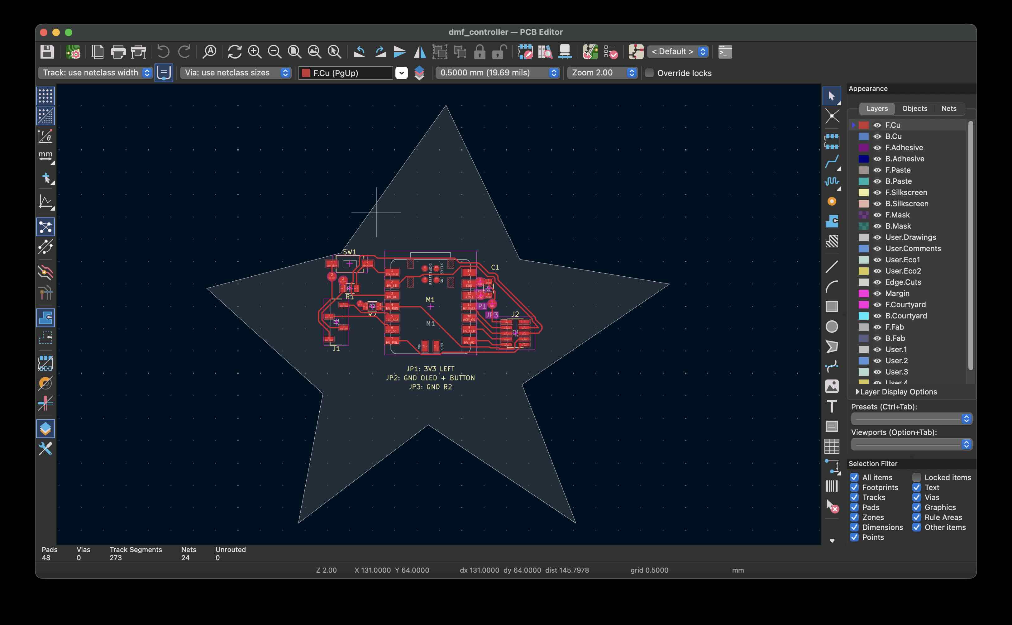
The checks found no ERC violations, no unconnected PCB items, and no electrical DRC errors.
Talk with Quentin
On the first review, I met with Quentin and we also talked about my final project.
We first discussed the high-voltage part of the project. He pointed out that the shop has power supplies, so I do not need to wait until I have designed and fabricated the driver PCB to test the principle. I could start with a 2 × 1 electrode test piece, place a droplet over one electrode, and apply voltage to the neighboring electrode. Using the power supply, I could gradually increase the voltage from low to high and observe whether the droplet moves. He suggested that I consider abandoning this approach if the droplet still does not move at high voltages such as 30 V or 50 V, because it could pose a risk of electric shock.
I could also try different electrode and droplet sizes. A smaller droplet might be easier to move, but evaporation could become a problem if it is too small. Keeping the test environment more humid could help slow the evaporation.
Quentin's another suggestion was ferrofluid. It can be controlled with a magnetic field, which sounds interesting too and would avoid the need for high voltage. He suggested using a voice coil or an electromagnet coil. With enough current flowing through the coil at a low voltage, it could generate a magnetic field to control the ferrofluid. An high current amplifier could drive the coil.
I plan to try both approaches later.