Electronics production
Assignment
This week's assignment is to make and test an embedded microcontroller system I designed. The group assignment is to characterize the design rules for the lab's PCB production process and submit a PCB design to a board house.
Starting design
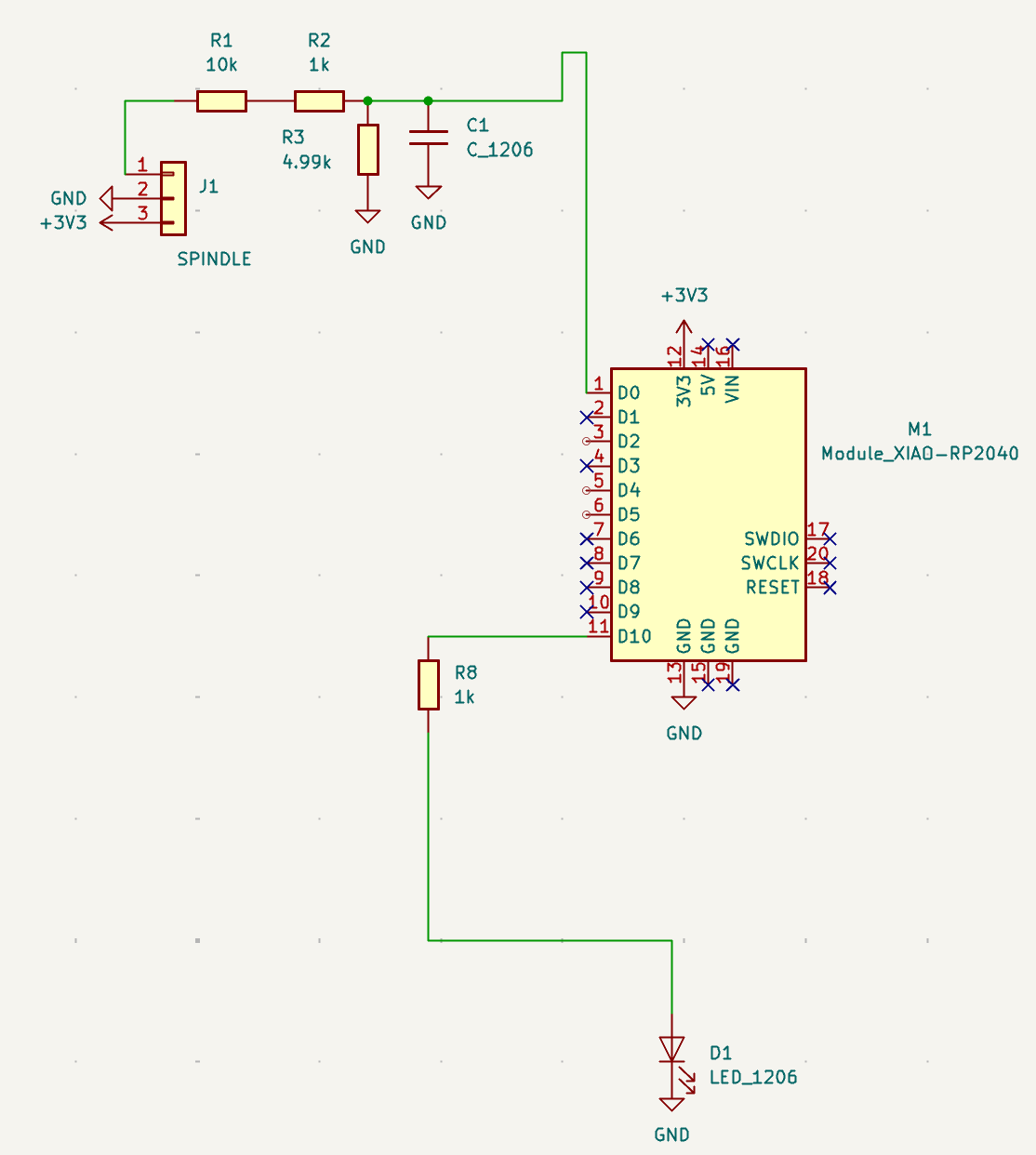
In electronics design, I laid out a spindle-sense breakout for the final-project mill in KiCad. These images follow the second revision from the schematic and PCB layout to milling and assembly.
Simplifying the circuit
For the second revision, I tried to make the board cleaner by simplifying the input circuit to just the voltage divider and the RC low-pass filter. I kept the XIAO RP2040 and an indicator LED.
The spindle input connects through the resistor network to D0 on the XIAO, with the filter capacitor connected from that node to ground. D10 connects to the indicator LED through a 1 kΩ resistor.
Footprints and routing
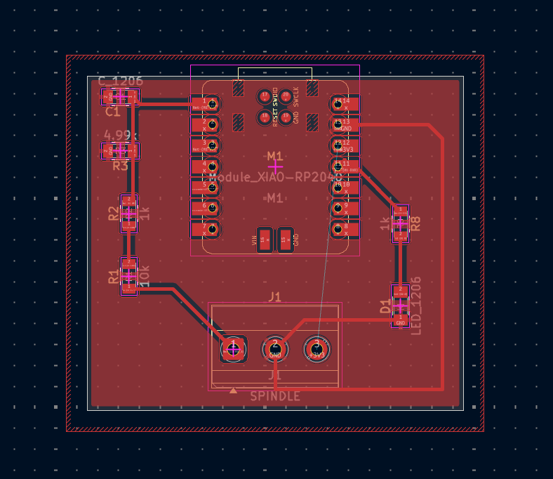
In the PCB layout, the XIAO footprint sits near the top and the spindle connector is along the bottom. The input resistors and capacitor are on the left; the indicator LED and its resistor are on the right.
3D preview
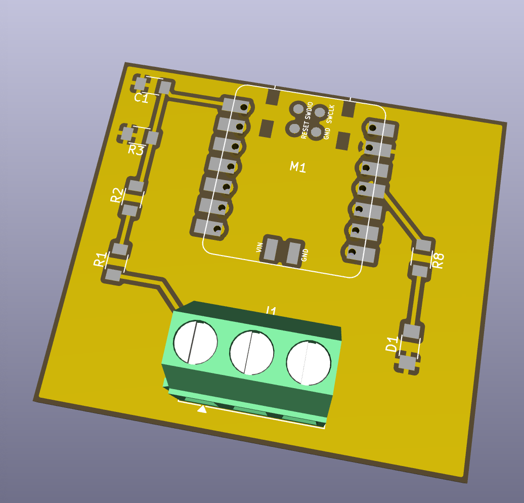
The 3D view shows the board outline, copper layout, and three-position screw terminal. The XIAO and surface-mount components are represented by their footprints and pads in this view.
Setting up the Carvera
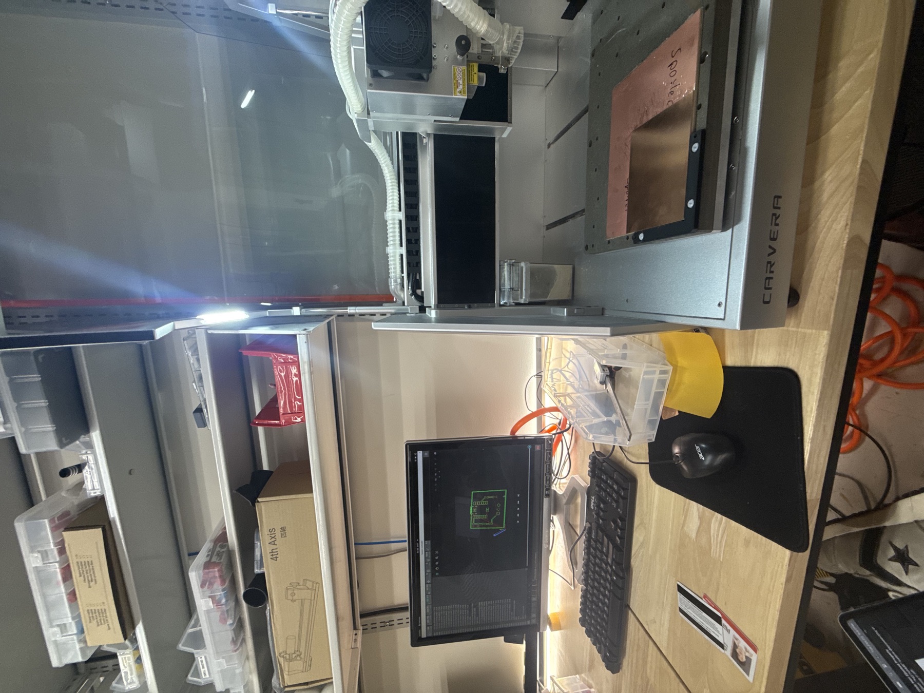
Before milling the board, I had to set up the Carvera. I had used the Carvera before, so I was already familiar with the machine.
Milled board
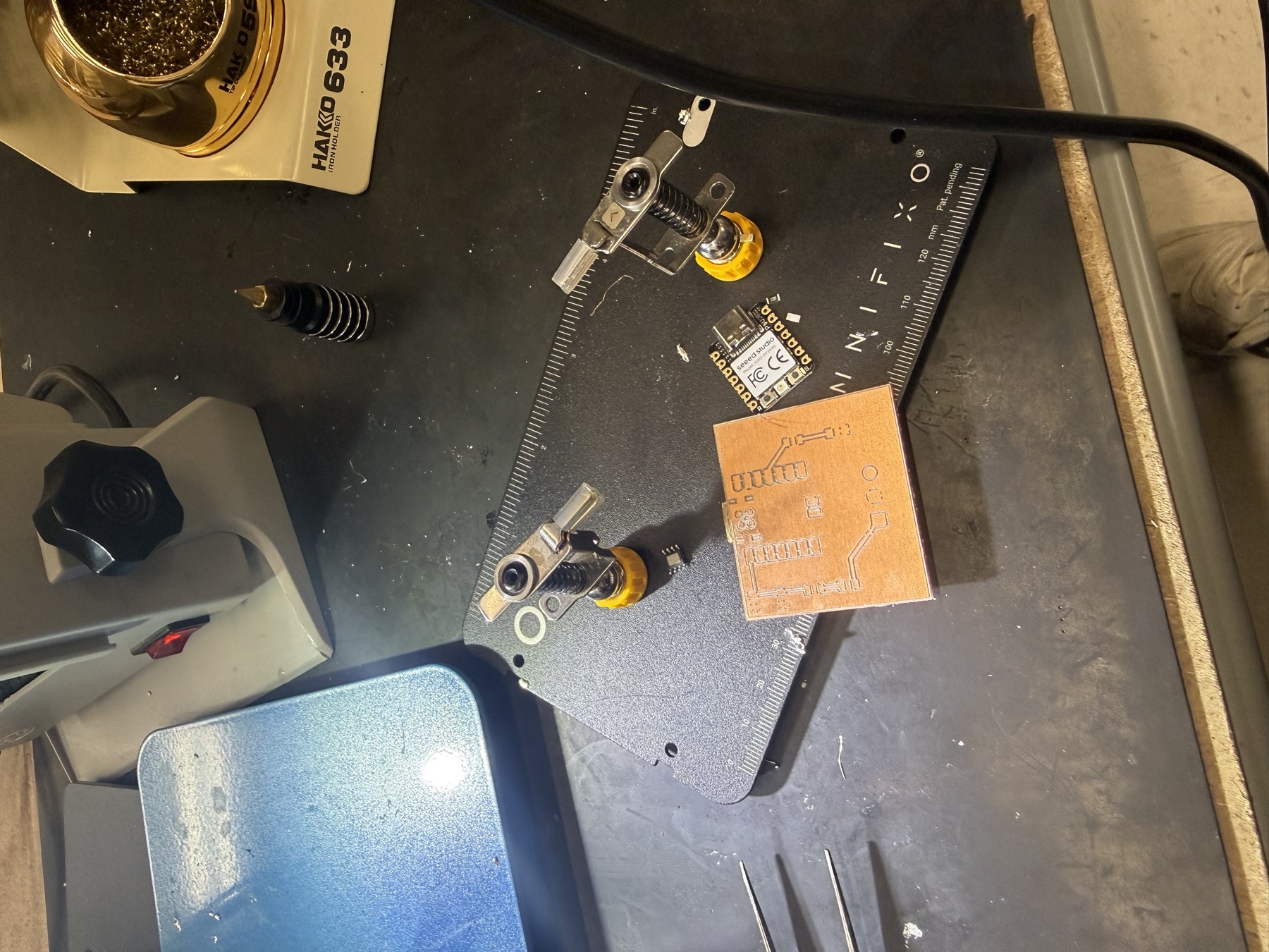
After milling the board, I brought it to the soldering bench. The copper traces and component pads are visible here, with the XIAO RP2040 beside the board before assembly.
Assembly under the microscope
I positioned the XIAO over its footprint and began soldering the connections under the microscope. The board sits in a holder that keeps it in place while I work.
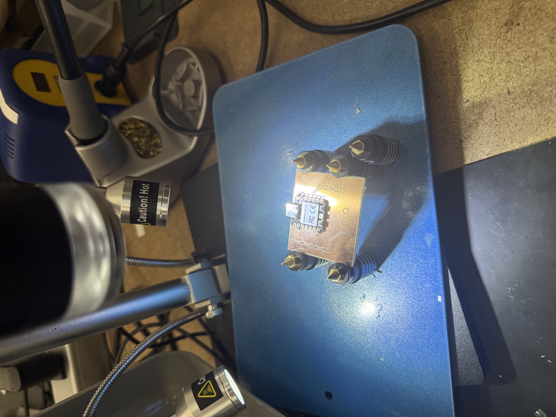
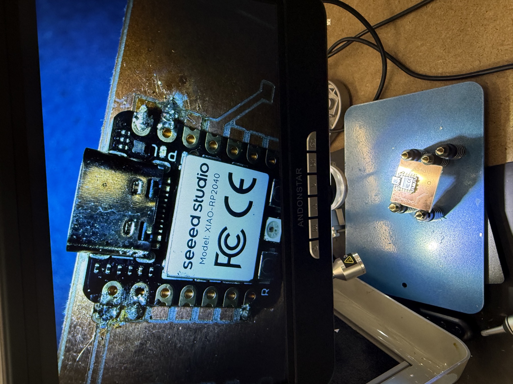
Documentation status. The documentation is incomplete beyond the last assembly photo above. Further assembly details and test results still need to be added.
Next mini-project: closed-loop motor speed control
In addition to the course assignments, I plan to make a board that controls the speed of a small brushed DC motor. It should reach and hold a target speed, using encoder feedback to measure the speed and adjust the motor's PWM drive.
Jake Read, the PhD student whose work is the inspiration for my final-project mill, suggested this as a small step before scoping out more of the mill. I have already bought the motor myself; the control board is the next thing I plan to produce.
Parts for the planned board
| Item | Part and details |
|---|---|
| Motor — already bought | JGA25-370 brushed DC gearmotor, 12 V, 150 RPM output, with a built-in Hall quadrature encoder. Wires: M+, M−, VCC, GND, A, and B. |
| Motor driver |
TI DRV8251A, part DRV8251ADDAR, in the SO-8
PowerPAD package. 4.5–48 V, 3.5 A peak, two-pin
PWM control through IN1/IN2, an IPROPI current-sense output,
and a VREF current-limit pin.
|
| Microcontroller | Seeed XIAO RP2040 or XIAO SAMD21, with 3.3 V logic and USB power. |
| Motor power | 12 V bench DC supply. |