Week05
Week 5: Electronics Production#
This week I milled and stuffed the base board I designed in week 4. It is the controller for the stationary base of my Vortex display: a XIAO ESP32-S3 that reads a knob and a hall-effect speed sensor and sends a PWM signal to the motor driver. Every module sits off the board and connects with jumper wires through right-angle headers along the edges.
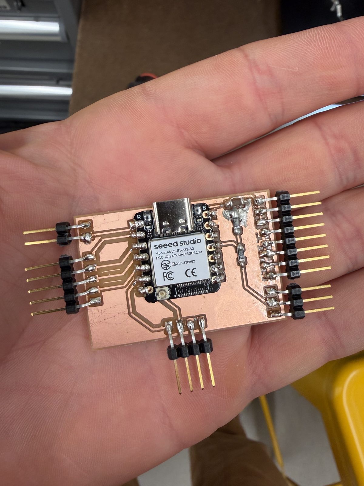
The design going in#
The board is single-sided, so no two traces can cross. Last week’s design got around that by separating power from signals. One 8-pin header (J5) carries 5V on pins 1 to 3 and ground on pins 4 to 8, and the other four headers carry signals only. Each module runs its own power and ground wires back to J5.
Before milling I went through the files one more time. The place I worried about was SDA and SCL, which run side by side only 0.4 mm apart. DRC passed because my clearance rule was also 0.4 mm, but a 1/64" end mill is 0.397 mm wide, which leaves the toolpath almost no margin. If the mill skipped that gap I would end up with a copper bridge between the two I2C lines. I rerouted SCL so it no longer runs alongside SDA. It now leaves the XIAO on a diagonal and drops straight down to J4, which puts about 2 mm of clearance between the two traces at their closest point. DRC stayed clean.
Milling#
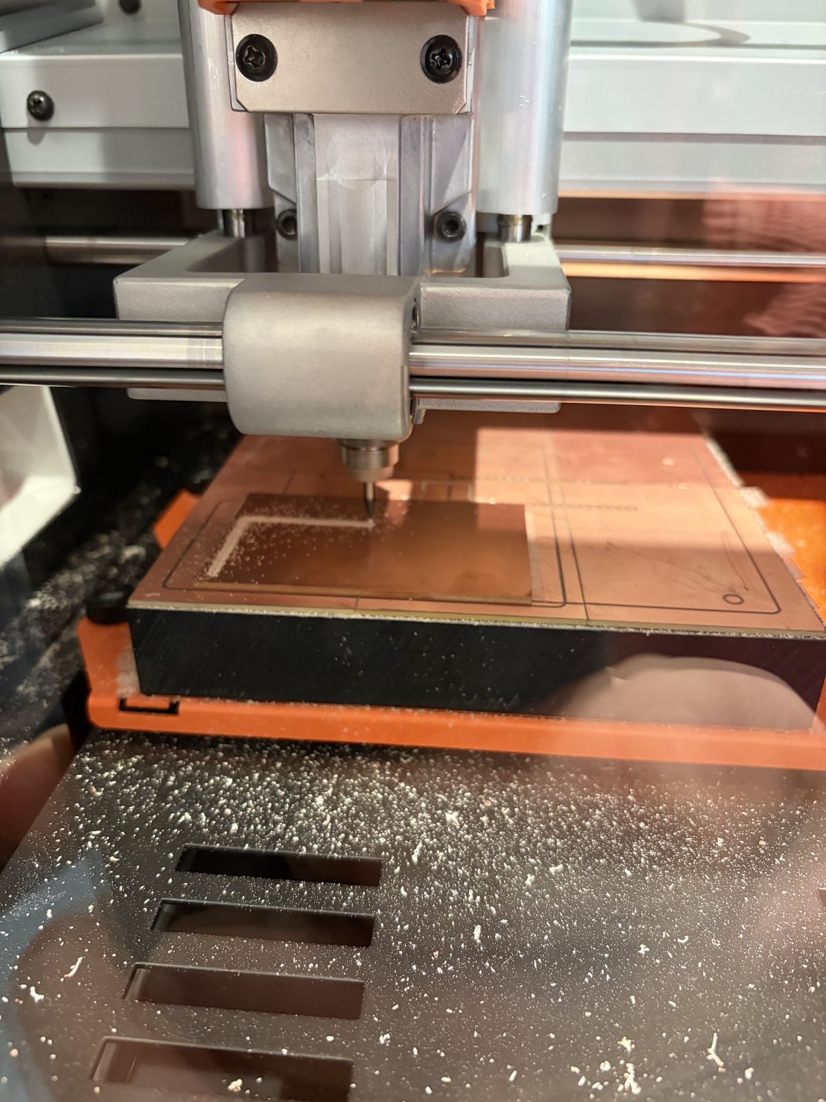
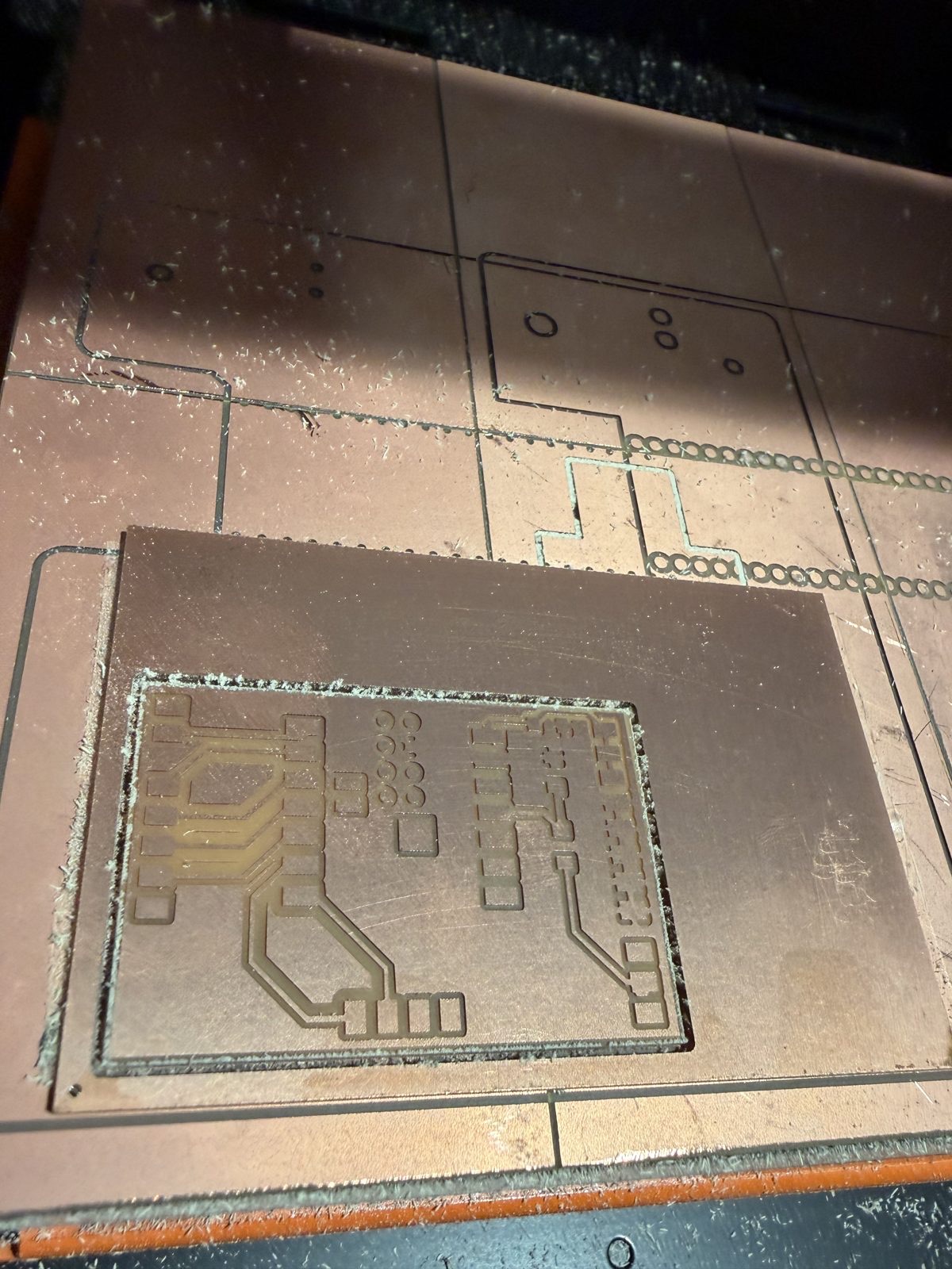
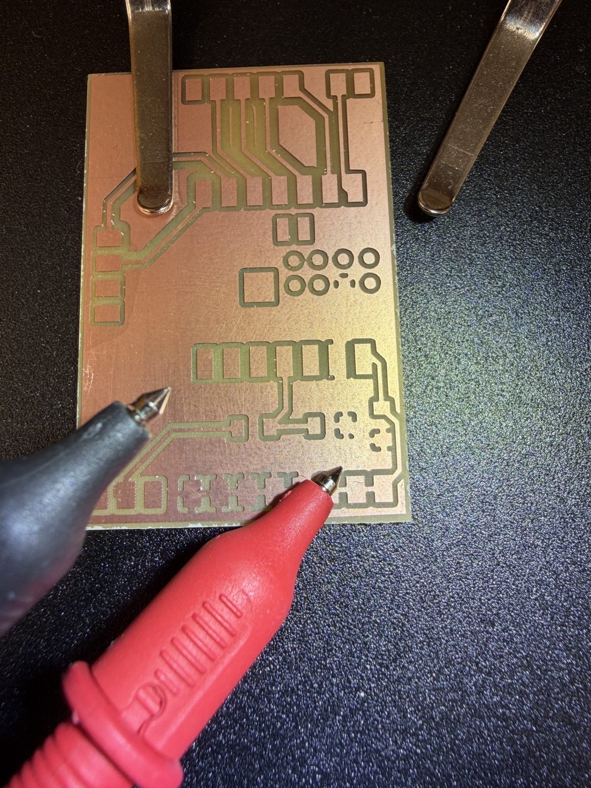
The board came off the mill clean. Every trace was isolated, including the SDA and SCL pair.
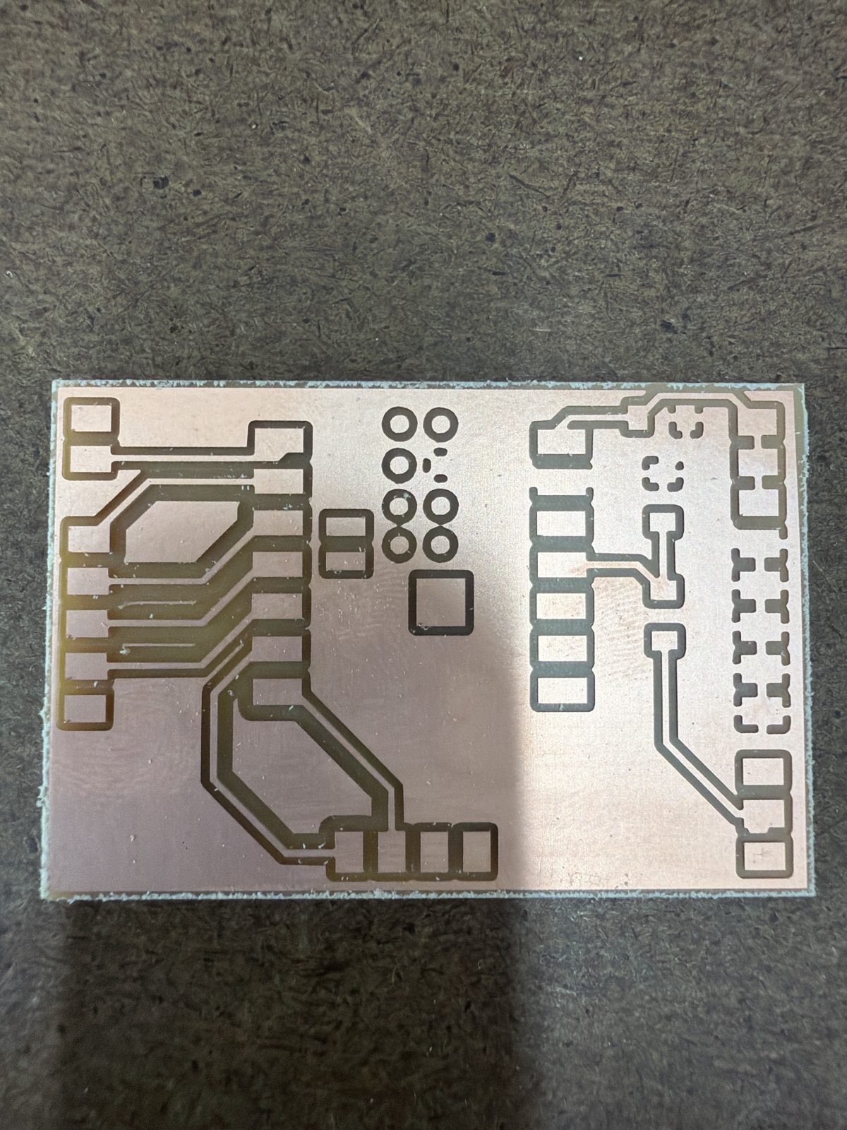
Two things looked like defects at first and turned out to be expected. The ground pads on J5 have broken outlines because they all sit on one ground pour, so the mill only cut around the outside of the group. The small pads under the XIAO are isolated islands, which keeps the module’s bottom pads from shorting to each other through the surrounding copper.
Before any soldering I scrubbed the copper, sanded the burrs off the edges, and used the meter’s continuity mode to confirm that 5V and ground were not shorted and that the SDA/SCL pair and the knob pins were all isolated from their neighbors.
Parts#
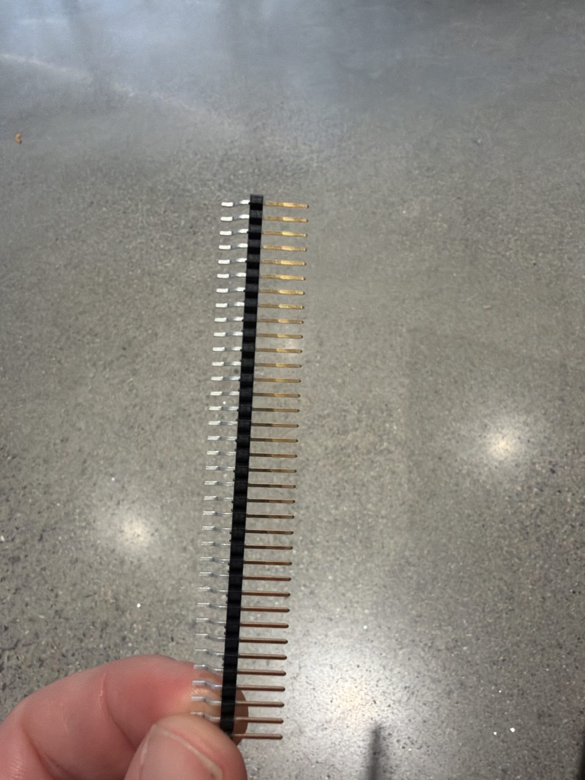
The bill of materials is short: the XIAO ESP32-S3, a 4.99k and a 10k resistor that form a voltage divider for the hall sensor, a 1 µF decoupling capacitor, and five headers cut from one strip. The passives are all 1206, a size code meaning 0.12 by 0.06 inches, which is about as small as I want to place by hand.
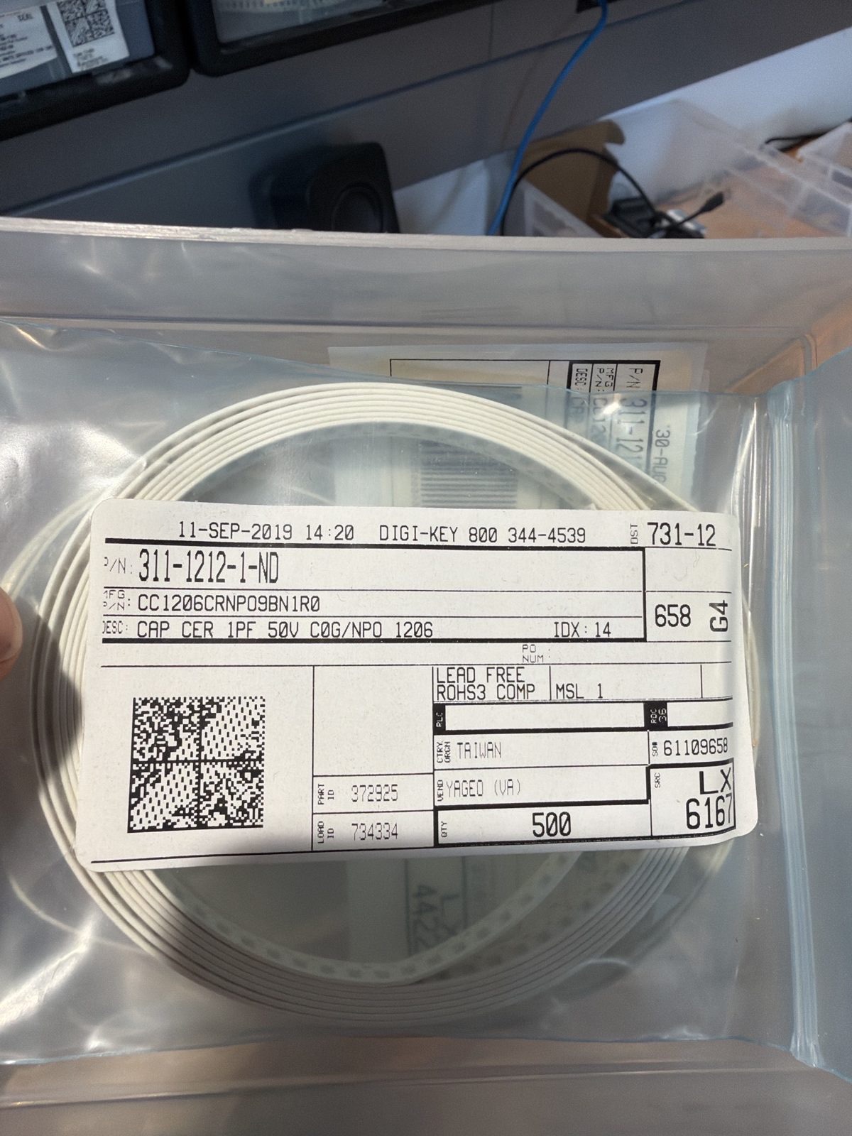
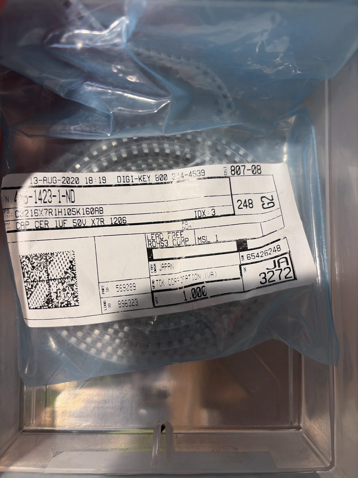
Reading the inventory labels carefully mattered more than I expected. The first capacitor bag I pulled held 1 pF parts, a million times too small. The right one reads “CAP CER 1UF 50V X7R 1206,” and the 105 in the part number is the giveaway.
I also found the parts for the next couple of weeks. The A1324 linear hall sensor comes in a SOT-23W package, so it will need a tiny breakout or wires soldered straight to its legs before a jumper can reach it. The ADXL343 accelerometer is an LGA package with its pads underneath, so that board will have to be reflowed rather than hand soldered.
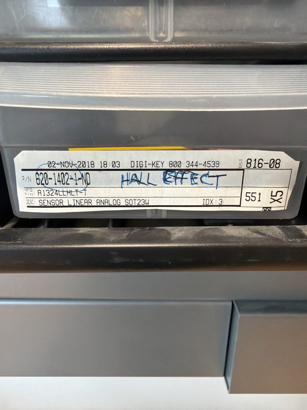
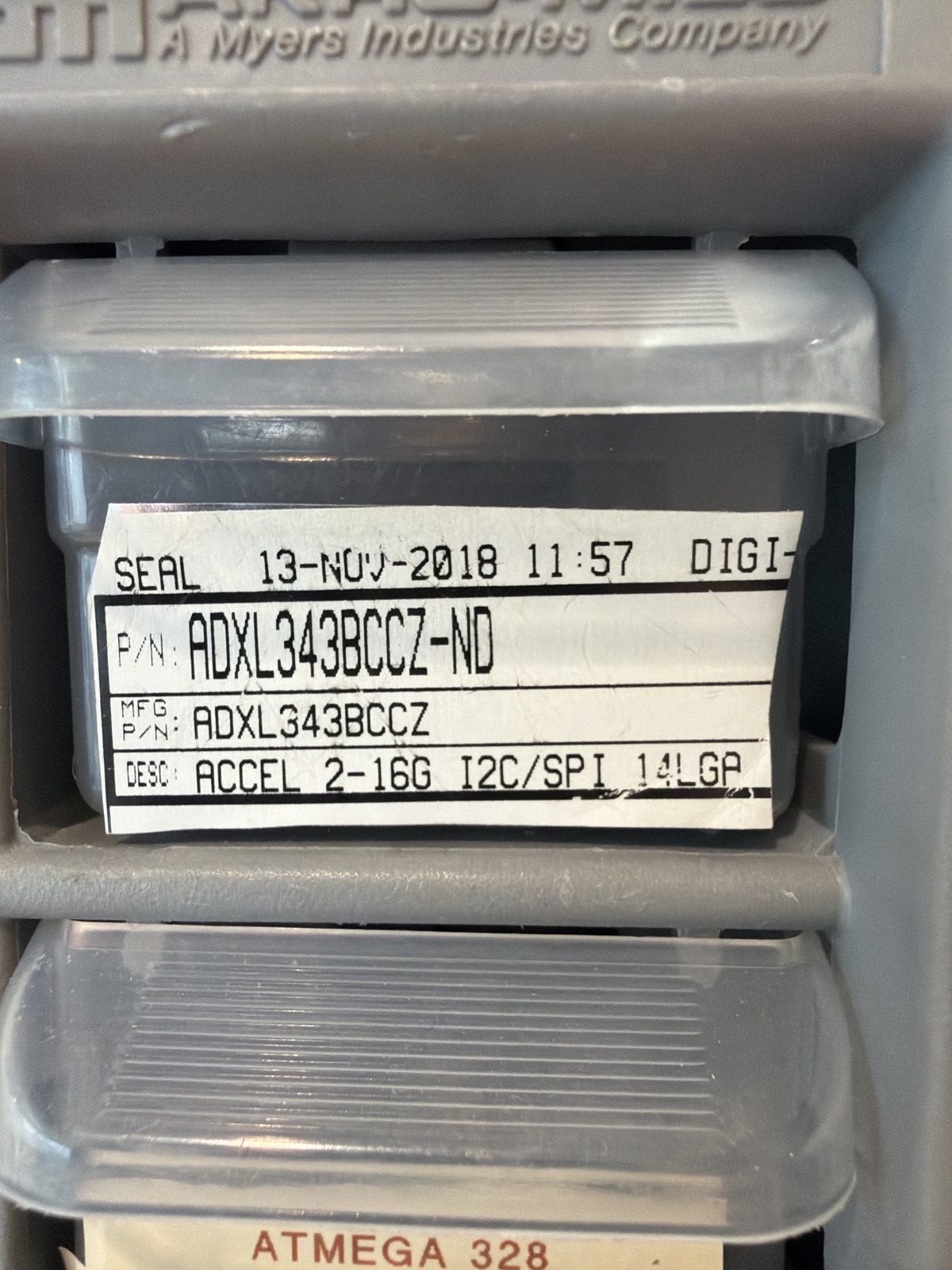
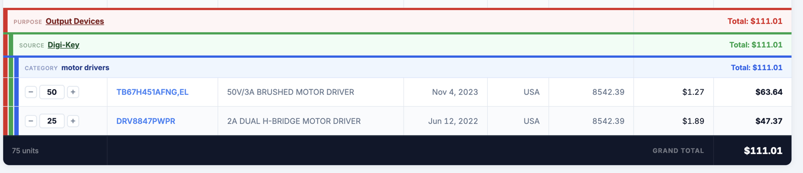
I checked whether a motor driver from inventory could stand in for the Pololu G2 I had planned to buy. The two in stock are the TB67H451 (50 V, 3 A) and the DRV8847 (about 2 A per bridge). A brushed 775 motor pulls several amps while running and far more at startup, so neither one is big enough. The choice stays between the Pololu and a brushless motor with an ESC, and this board works with either because both take the same PWM signal on D0.
Soldering#
I worked from the smallest parts to the tallest. R1 went down first and read 4.985k on the meter, comfortably within tolerance of 4.99k.
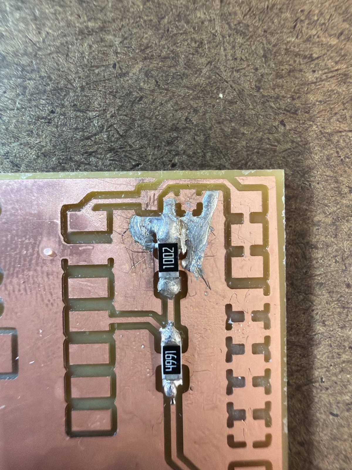
R2 did not go well. Solder balled up on the iron instead of flowing onto the pad, and when it finally let go I had a blob spread across the ground copper around the resistor. The desoldering braid would not pull it up no matter how long I held the iron on it, and I was holding it there for six to ten seconds at a time, long enough to risk lifting copper off the board.
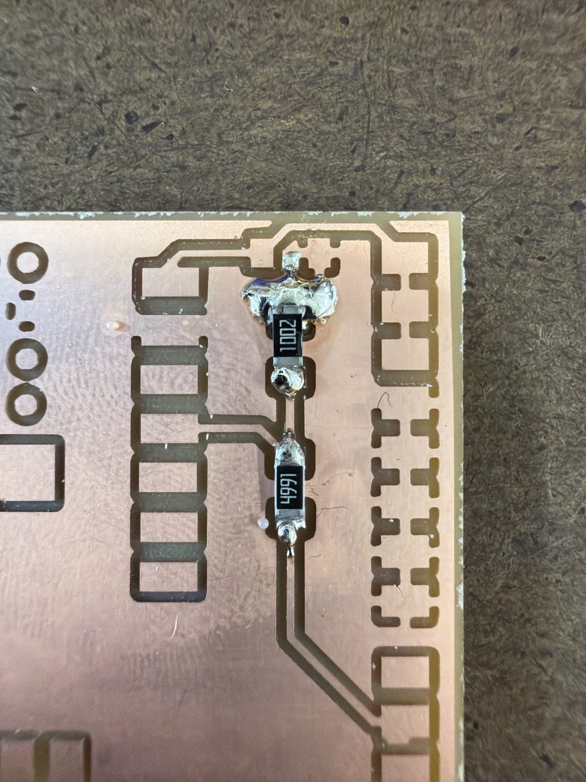
The real problem was the iron. Its tip was black with oxidation and passed almost no heat. I swapped the tip, and when the very end of the new one still would not take solder, I swapped it again. What actually fixed things was tinning: melting solder onto the hot tip until it is shiny, giving it one wipe on the brass cleaner, and keeping a coat on it the whole session. After that, joints took a second or two and the braid wicked solder up almost immediately. Most of the evening’s trouble came down to the condition of that tip.
The R2 cleanup mattered because C1 sits just above it. C1’s right pad is ground, so solder touching it there does no harm, but its left pad is 5V, and any bridge to the surrounding ground copper would short the board. I wicked the smear back from the 5V side, soldered C1’s ground end first, and put only a touch of solder on the 5V end. The meter confirmed no short between 5V and ground, and each end of C1 beeped through to the right pins on J5.
Two multimeters with dying batteries also cost me time before I found one that worked.
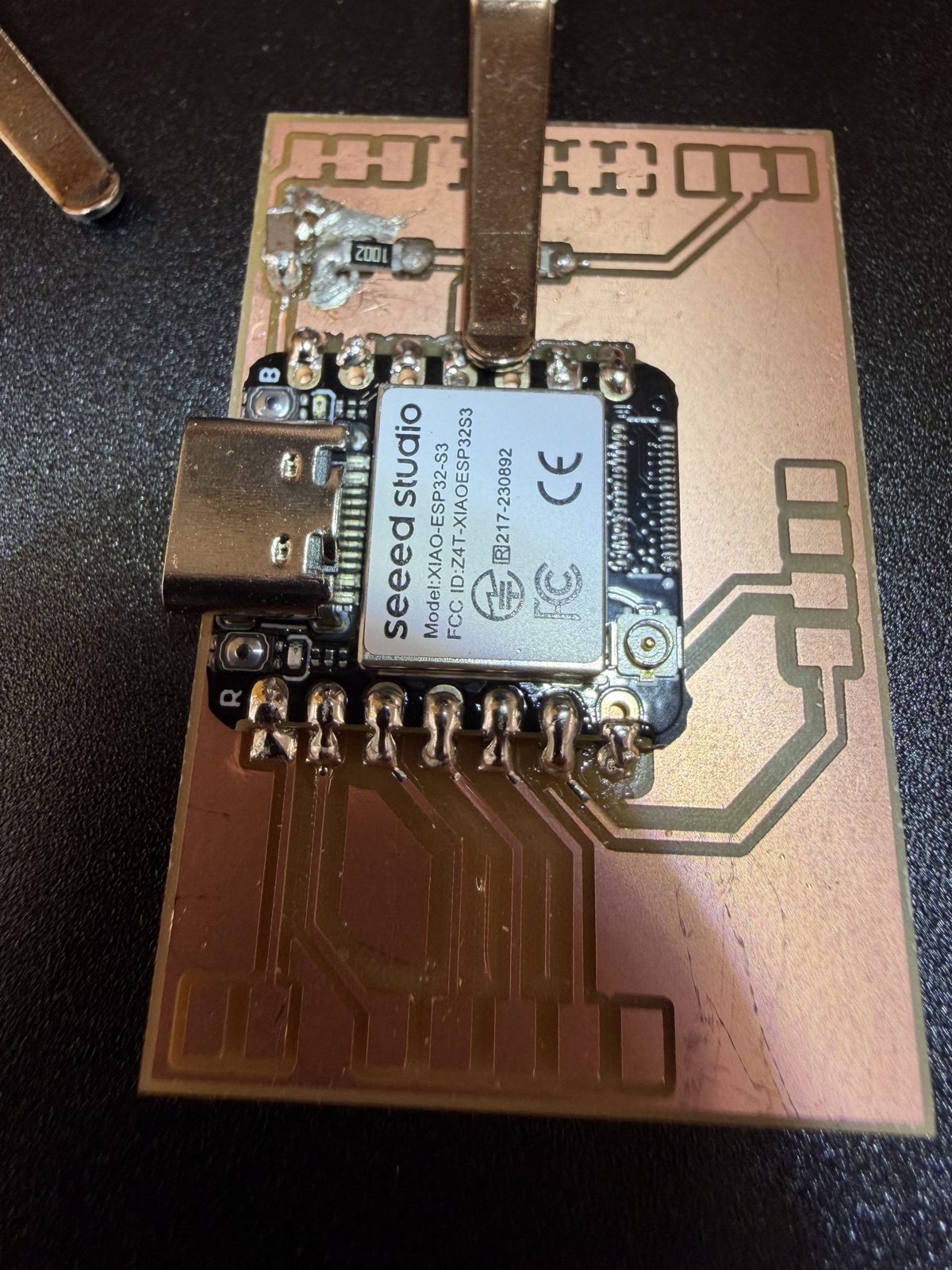
For the XIAO I tacked two opposite corners and tested both tacks before soldering the rest. The test that matters puts one probe on top of the XIAO’s half-hole rather than on the board pad, and the other wherever that pin is supposed to end up. That checks the whole joint and catches solder that looks fine but never actually bonded. J1 is rotated on the board, so its pin 1 is not the top pad, which cost me a confused minute. After soldering the remaining pins I tested every one against its header and against its neighbors.
The headers went faster once I put a bead of solder on one pad first and then melted the header foot down into it, which frees up a hand for holding the part. The copper pad under J2’s third pin lifted off with the header, but nothing connects to that pin, so I left it alone. Testing J5 caught two bad joints: ground pins 5 and 6 did not beep against the rest of the ground pins. Reflowing both fixed them.
Power-up#
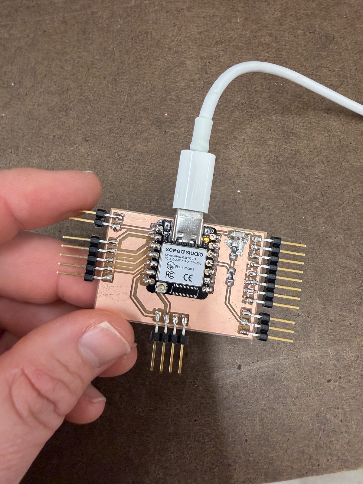
After one last check for a short between 5V and ground, I plugged in USB. The computer detected the board, the XIAO’s LEDs came on, and nothing got warm. The meter read 5.249 V across J5, so power is reaching the header that every module plugs into.
What I learned#
The biggest lesson had nothing to do with my board. An untinned tip oxidizes and stops passing heat, and no amount of time or pressure makes up for it. Once I kept the tip tinned, my soldering improved more than it did from anything else I tried.
Testing every pin with the meter was worth the extra time. Two of J5’s joints looked soldered and were not, and I would never have caught that by eye.
Less solder is better. The R2 blob started with too much on the first pad, and cleaning it up took longer than soldering everything else on the board.
Next#
I still need to upload a blink sketch to confirm the XIAO programs. After that, the hall sensor gets wired up with a magnet for input devices week, and the rotor board is the next board to design.
Files#
Use of AI#
Use of AI in this assignment: the fabrication this week was mine. I milled the board, stuffed it, and tested every joint with a meter, and the mistakes along the way were my own to find and fix. I used Claude as a tutor around that work, mostly to check my understanding before and after I measured something, and to interpret what I was seeing when the meter disagreed with what my eyes told me. The wrong 1 pF capacitor and the solder blob on R2 were both caught at the bench, not by asking.