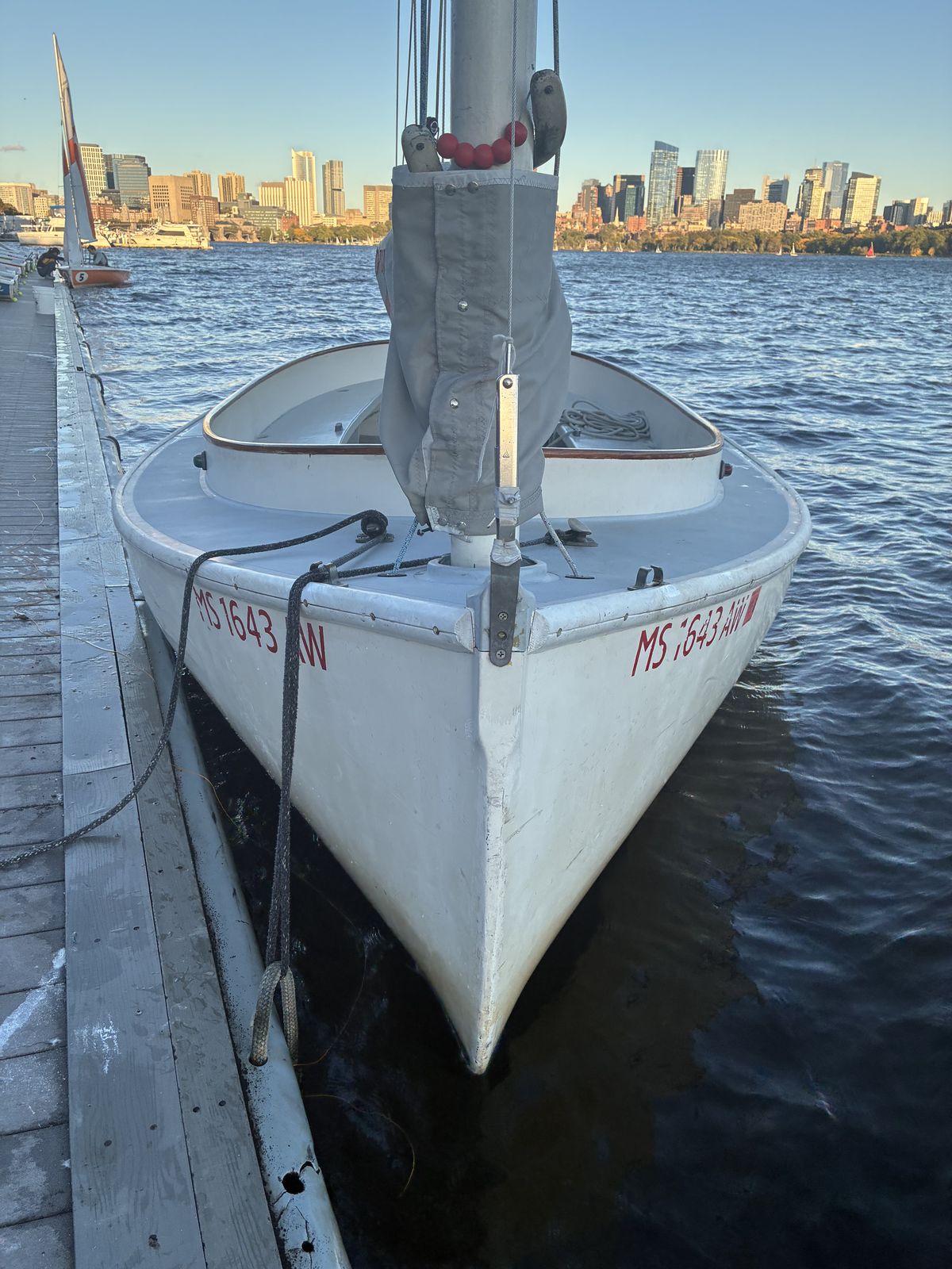
A remote-controlled boat
WIP
Choosing the boat was the hard part, and probably the longest one. There are a lot of boats I find really graceful and that I would happily have built, and I wanted to pick the right one.
What settled it was sailing a catboat for the first time, this weekend (October 4, 2026). I loved the way it slid on the water, how elegant it is, and how smooth it felt to sail. It also felt like the logical choice: the catboats I sailed belong to the MIT Sailing Pavilion, and they were built at a boat yard in South Orleans, Massachusetts.
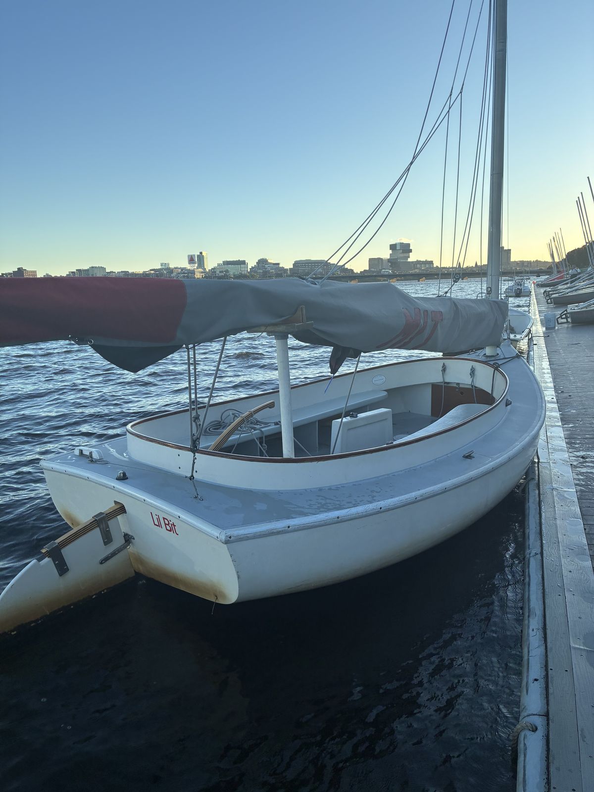
So I got in touch with the MIT Sailing Pavilion, and they let me go through their archives to look for plans or a contact name. I did not find the exact plans I wanted, but I did find the boat yard: Arey's Pond Boat Yard. I have contacted them.
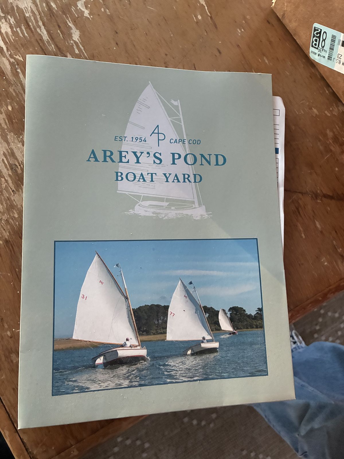
Once they get back to me, the plan is to draw the hull in Fusion and print it in several parts, splitting it in the slicer. Then I will glue all the parts together and use composite on top to make it waterproof.
Update: I still have not heard back from Arey's Pond. Rather than wait forever, I decided to get started and take the measurements of the boat myself.
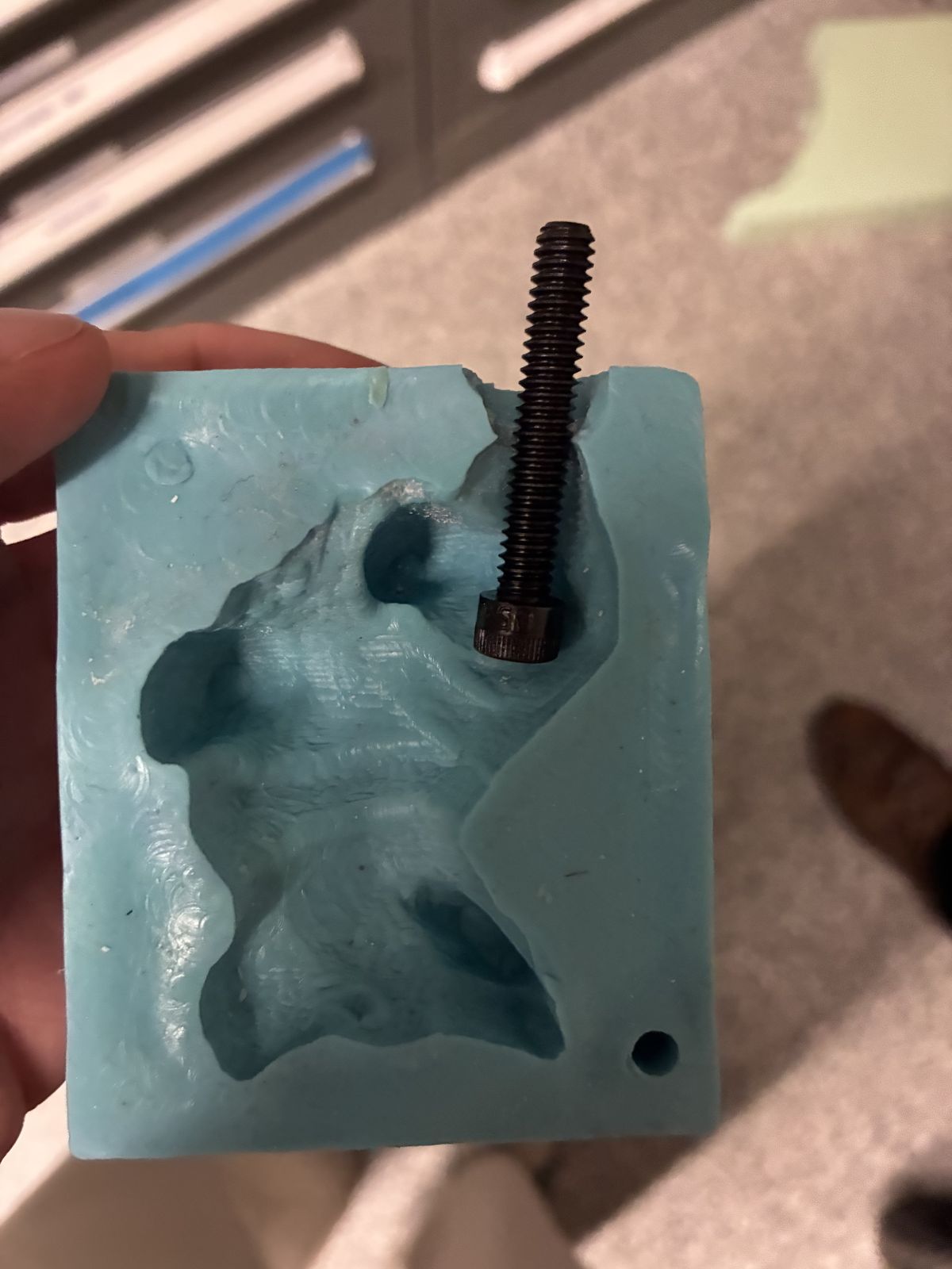
I want to cast the centerboard in metal. It needs to be heavy enough to balance the force of the wind on the sail, but not so heavy that it slows the boat down too much.
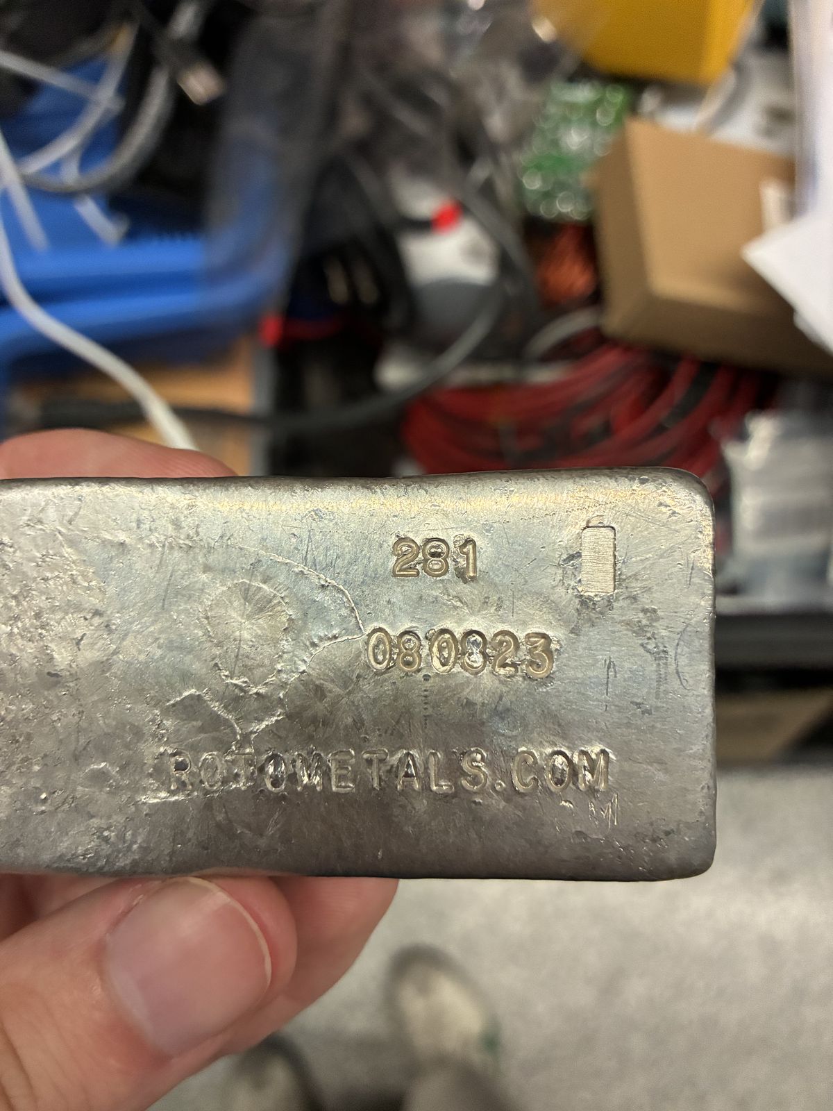
I still need to check with Anthony exactly which metal this is.
I also want to cast it around a screw, so that the screw sticks out of the centerboard and I can use it to attach it to the boat.
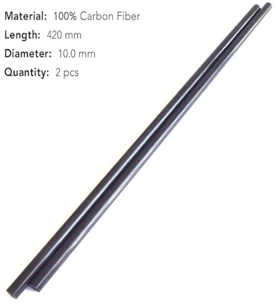
Two carbon fiber rods: one for the mast and one for the sprit.
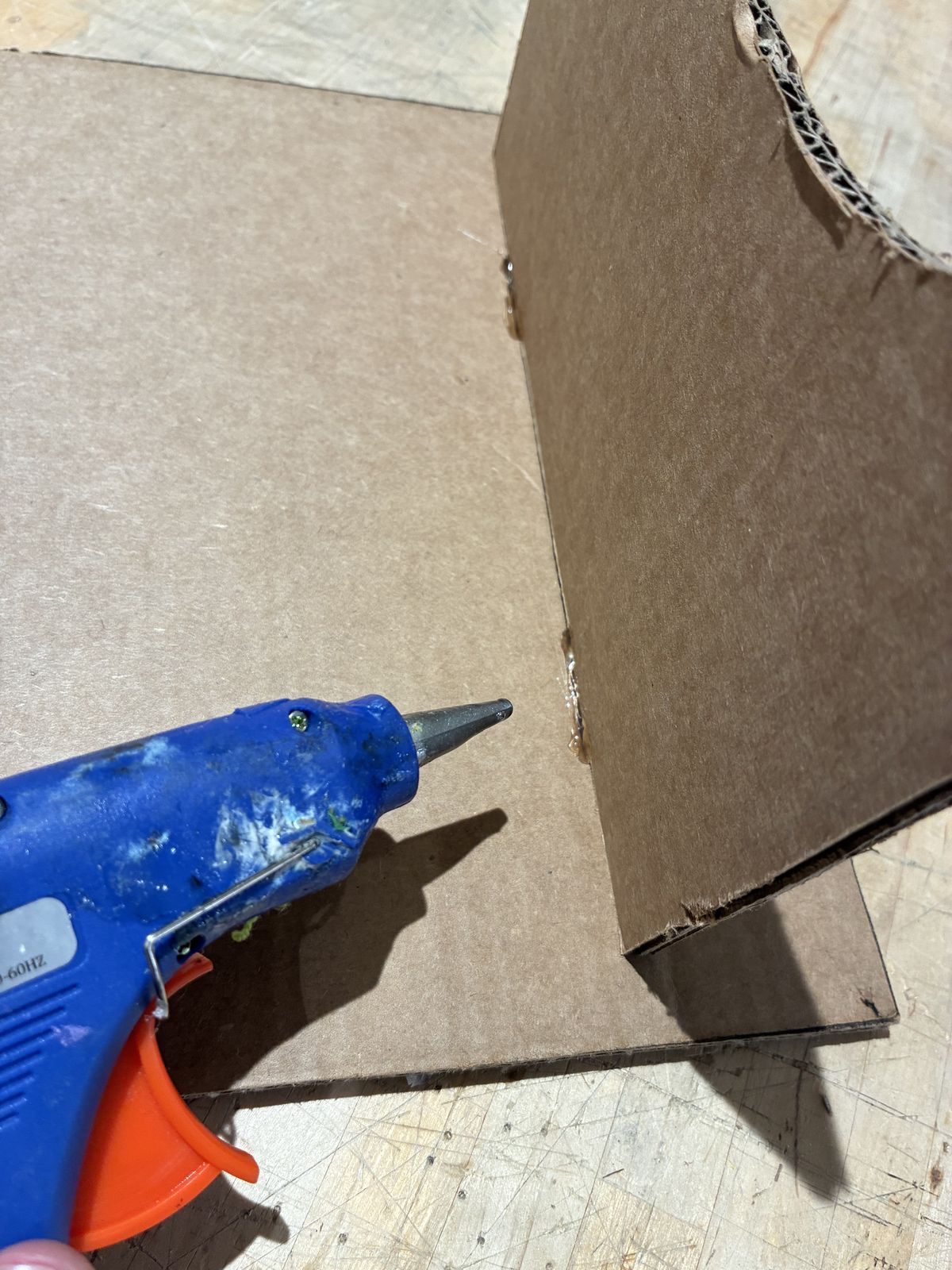
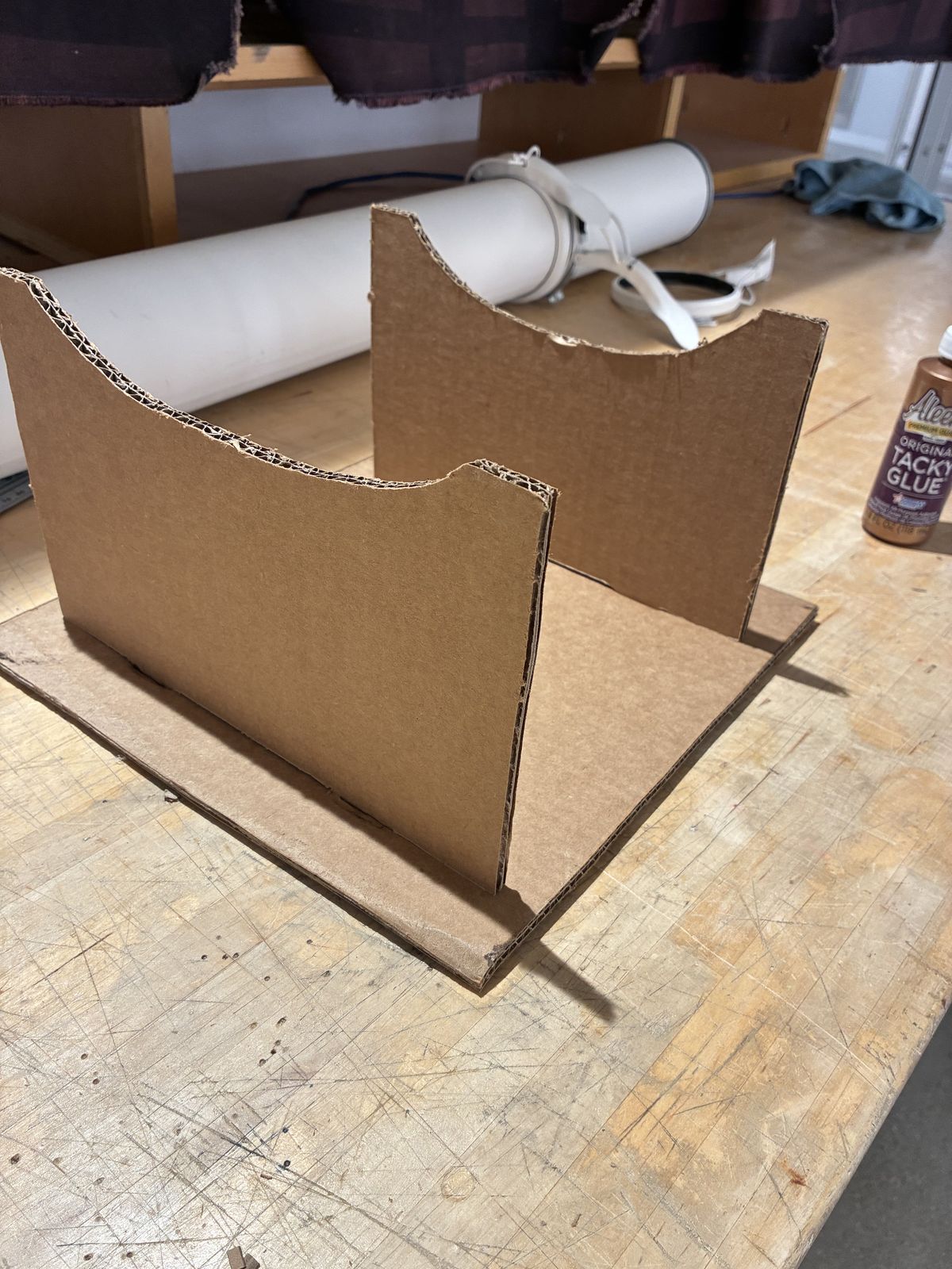
A boat does not stand up on its own on a table: with its centerboard it would rest on the keel and tip over, and without it the hull is rounded, so it just rolls onto its side. I will need somewhere to put it while I work on it. So I built a holder: a cardboard cradle, with two upright supports whose top edge is curved to follow the shape of the hull, slotted into a flat base.
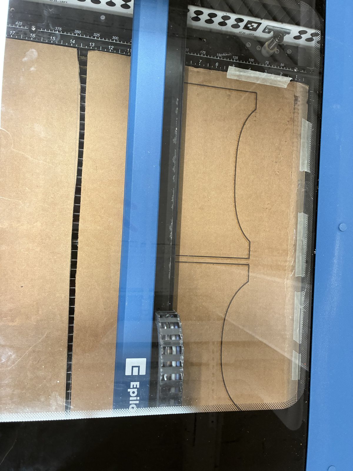
I drew it in Fusion, with a sketch of each piece and an extrusion to the thickness of the cardboard. Then I tried the laser cutter. It barely cut: the lines are there, but they did not go through the cardboard.
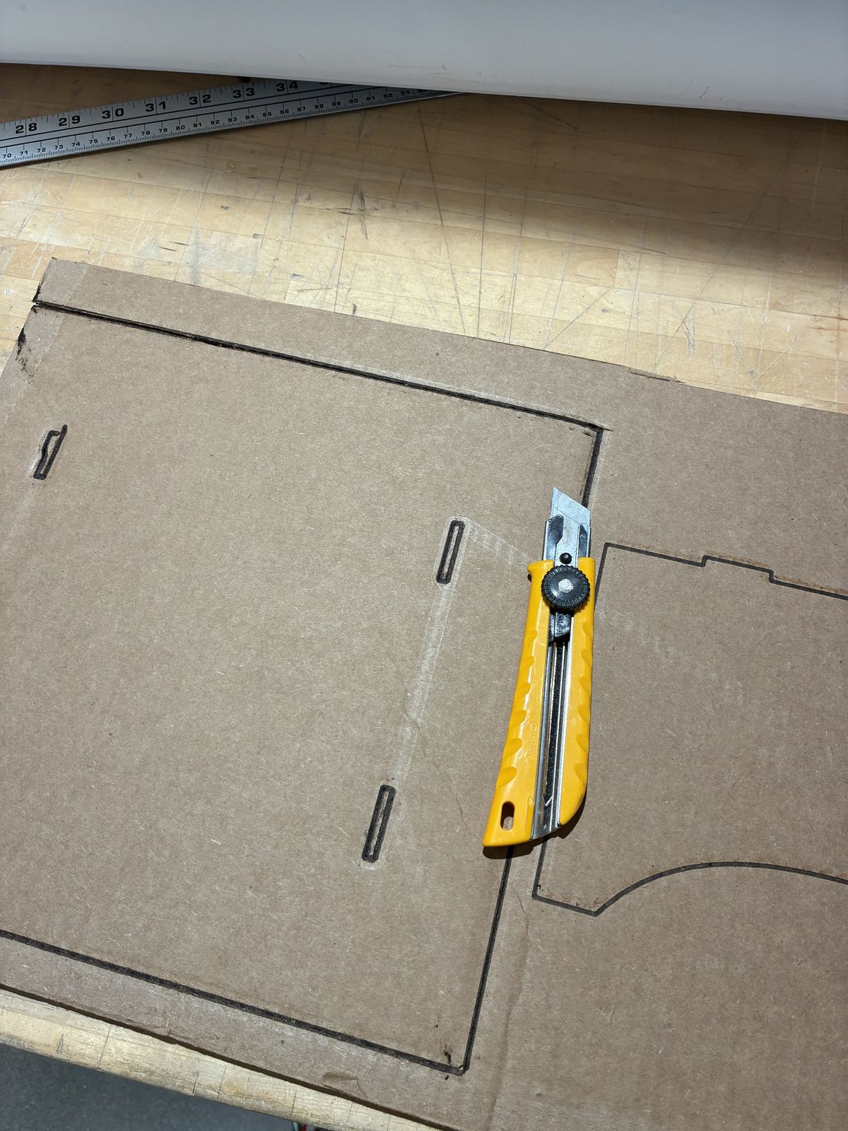
So I went back to the old method: the cutter. The laser lines turned out to be very useful as a guide, so I followed them by hand.
Once all the pieces were out, I slid the supports into the base and, for solidity, glued everything together with a glue gun.
WIP
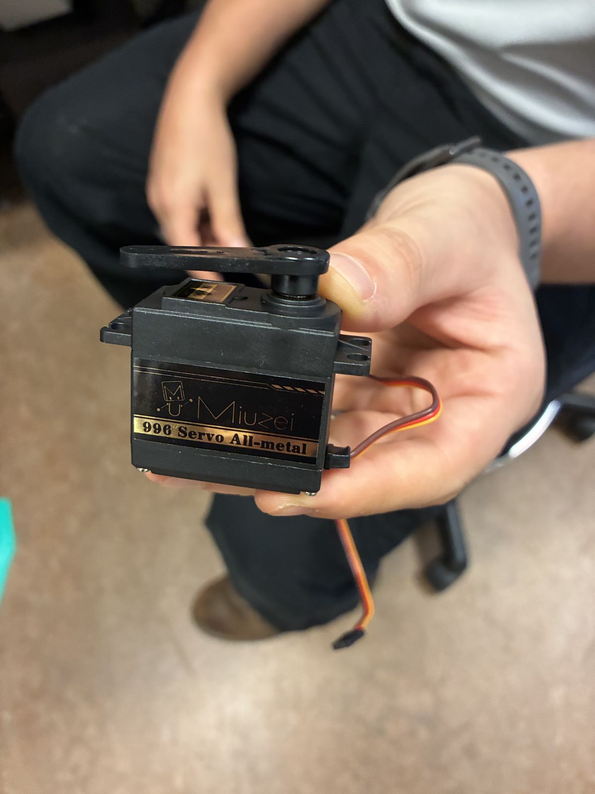
I will use two of these servos: one to steer the rudder and one to trim the sail. The MIT Sailing Pavilion has already allowed me to use a bit of their very thin line for it.
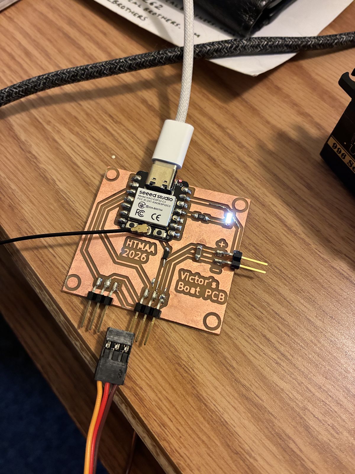
The brain of the boat is a small circuit board that I designed in week 5 and made in week 6. Those two weeks were really the start of the electronics of this project, so here is the short version. The week pages have all the details and all the mistakes.
The plan. Before touching any software, I drew in my notebook who talks to whom: a remote (or my phone) talks wirelessly to a microcontroller, which drives two servos, one for the rudder and one for the sail, and a battery pack feeds everything.
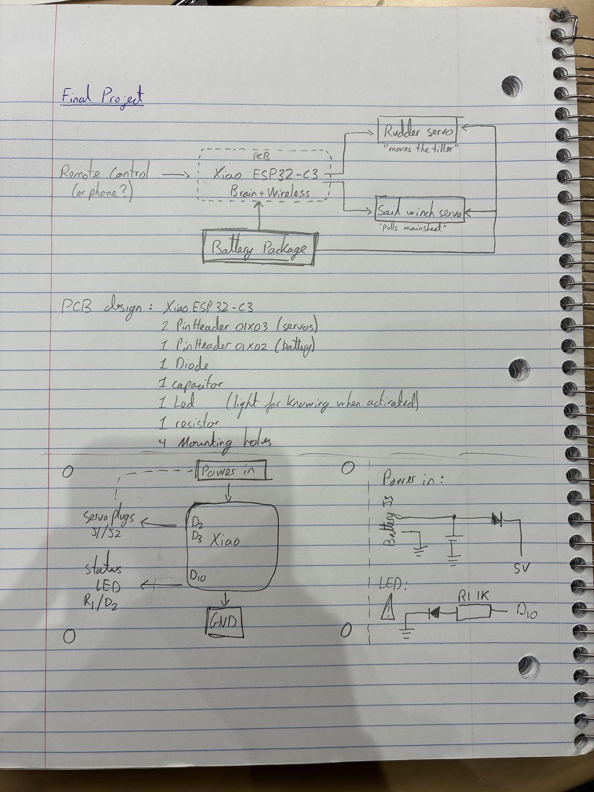
The parts. The microcontroller is a Seeed XIAO ESP32-C3, because it has Wi-Fi and Bluetooth built in, and a remote-controlled boat with no way of being remotely controlled is just a boat. The servos plug into the board through 3-pin headers, and the battery through a 2-pin one. On the board there is also a Schottky diode, a capacitor, and a status LED with its 1 kΩ resistor.
The design. I drew the schematic and the board in KiCad. The hard part was routing everything on a single layer of copper without tracks crossing or running under the bare header pins. It took several attempts, and two more redesigns in week 6: one to bring the tracks into the headers from behind, and one after Qilmeg pointed out that servo plugs have a fixed wire order (signal, +, −), which my sail header did not respect.
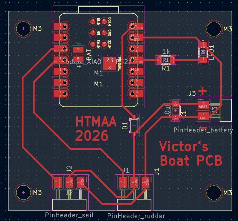
Making it. I milled the board in the lab. The tracks came out well, but the bit for the outline broke, so I finished cutting it out with a cutter and sanded the edges. Then came the soldering, which was slower than I expected: the parts are tiny, I first fought with cold joints until I changed solder wire, I could not tell which way round the LED went, and I tore off a bit of copper on the way, which I repaired by soldering a piece of wire in its place.
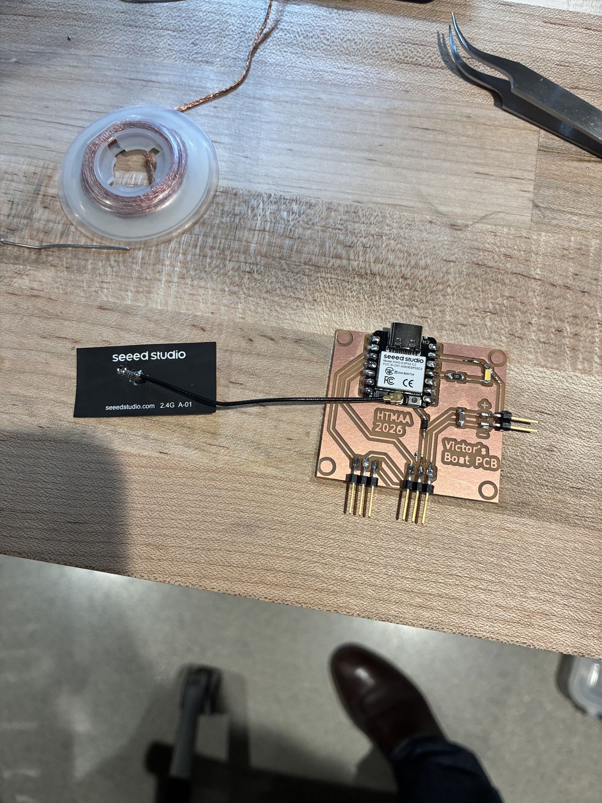
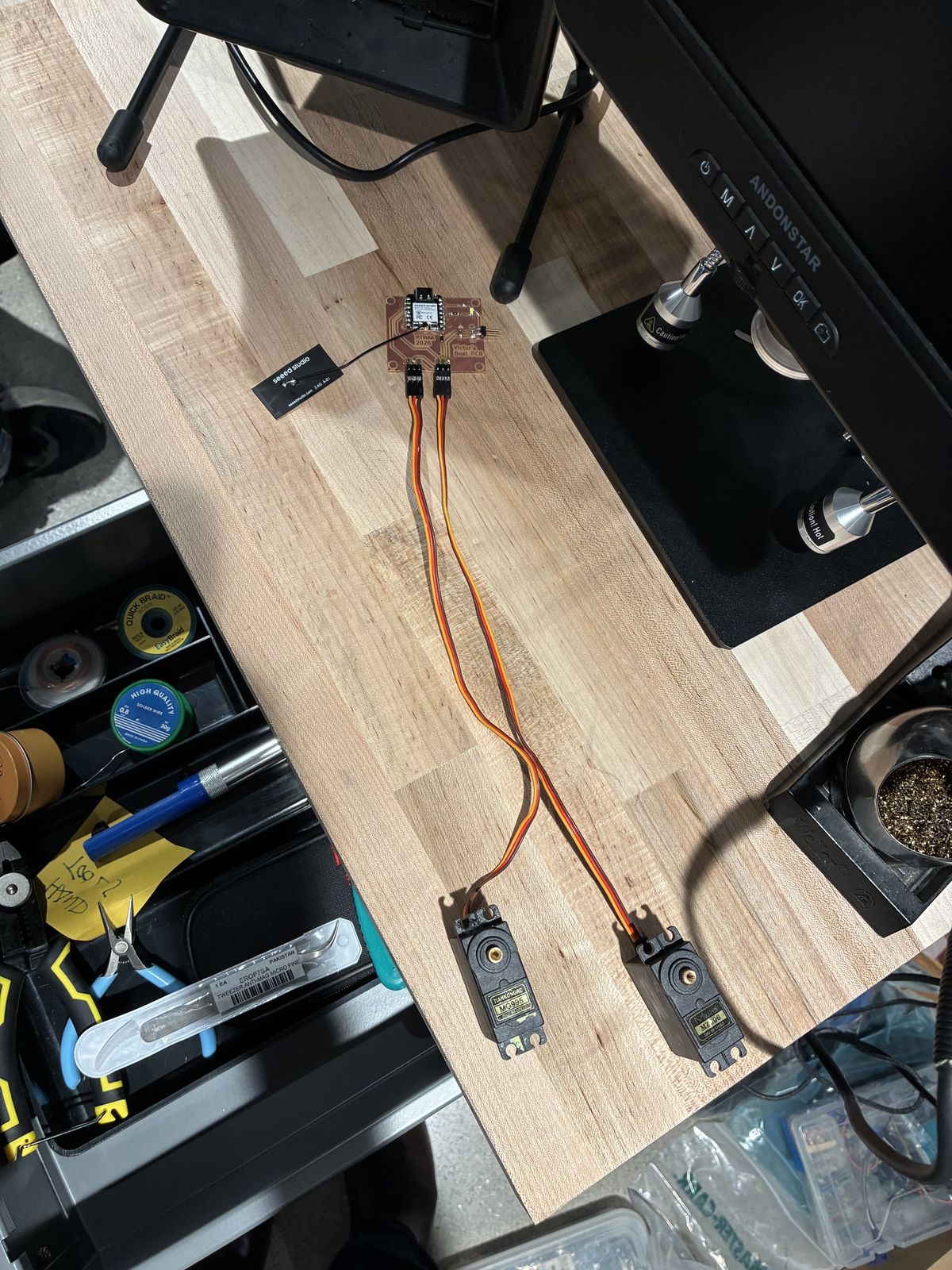
First test. I don't have a battery yet, and the diode stops the USB power from reaching the servos, so for now I could only test the LED. A small program blinks it on D10 and prints a message to the computer.
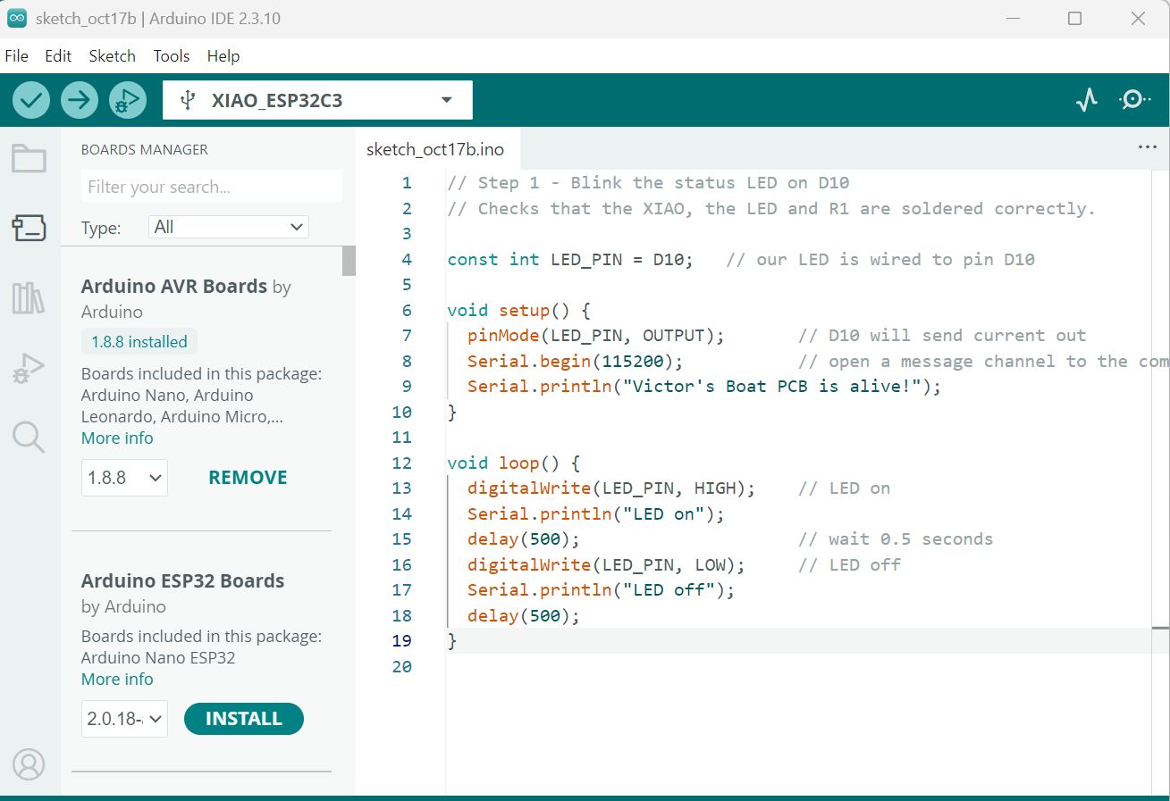
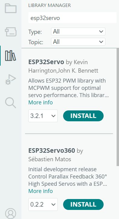
Next. Get a battery, and make the servos move. On the ESP32, servos are driven with the ESP32Servo library, so that is the next thing to install.
WIP
WIP
WIP
WIP
The fun part, for later: an oar, little people on board, and whatever else I think of.