Electronics Production

This week I am milling and testing the Castform board.

Schematic Revision

For context, I intend to build a Castform machine that knows how to auto-rotate. You can also refer to my design in Week 5 to see where I started.

During this week, I brieftly chatted with Anthony about the board design and had some ideas I want to put in before actually milling the board. The first change is that, in contratry to my prior belief, the 3.3V logic from the microcontroller itself would be enough for driving the LED lights. So I took out the logic buffer previously used to convert 3.3V to 5V and made the entire design possible with in house components. Besides that, I also decided to minimize through hole components and use more surface mount components to reduce milling and soldering complexity. This involved me swapping all the existing through hole connectors and capacitors for surface mount counterparts. Though I will be keeping four holes on the edge for potential mounting. I produced the new schematic below.
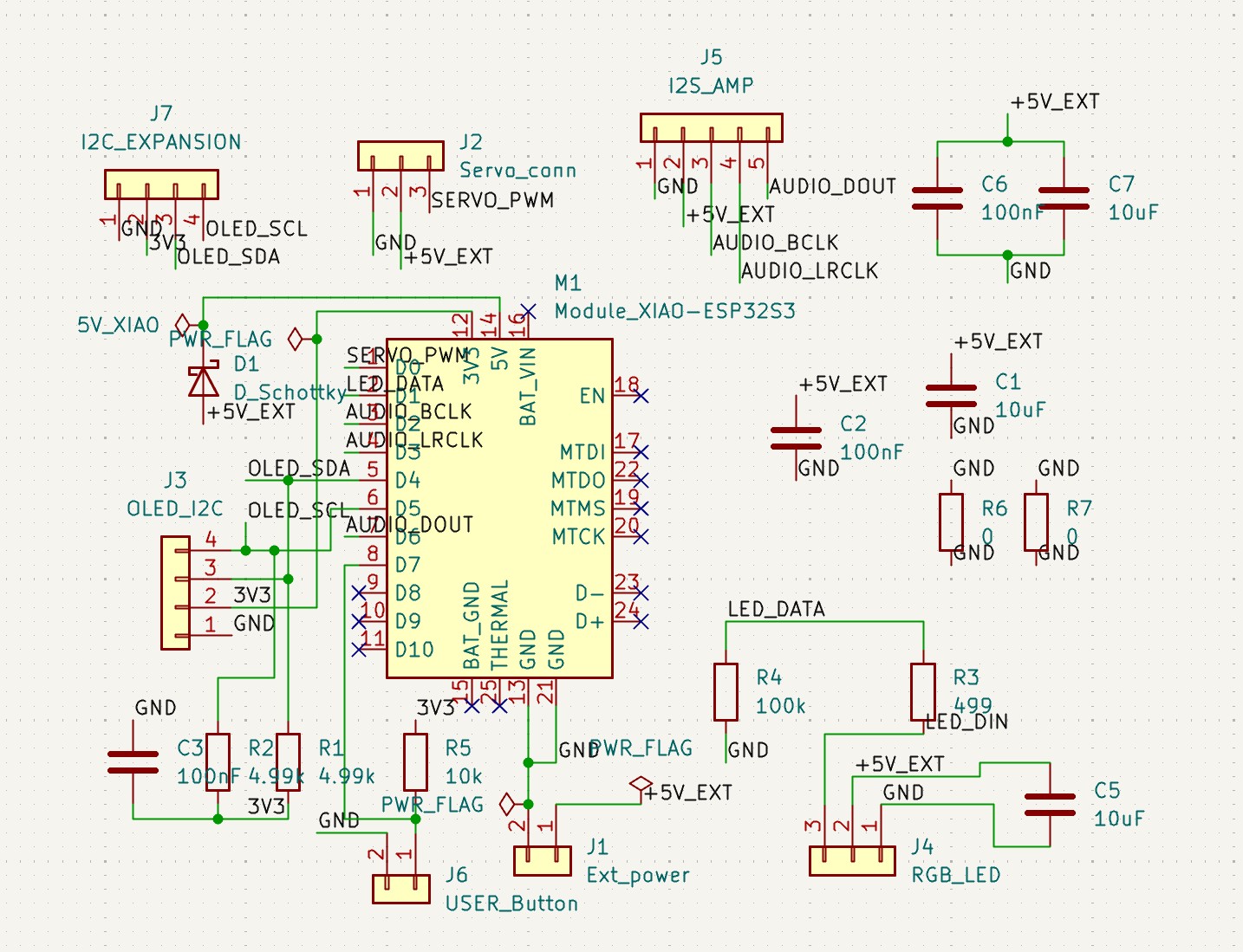
Schematic revision
Revised schematic. You can see the logic buffer U1 is removed and all the LED lights are directly connected to the microcontroller.
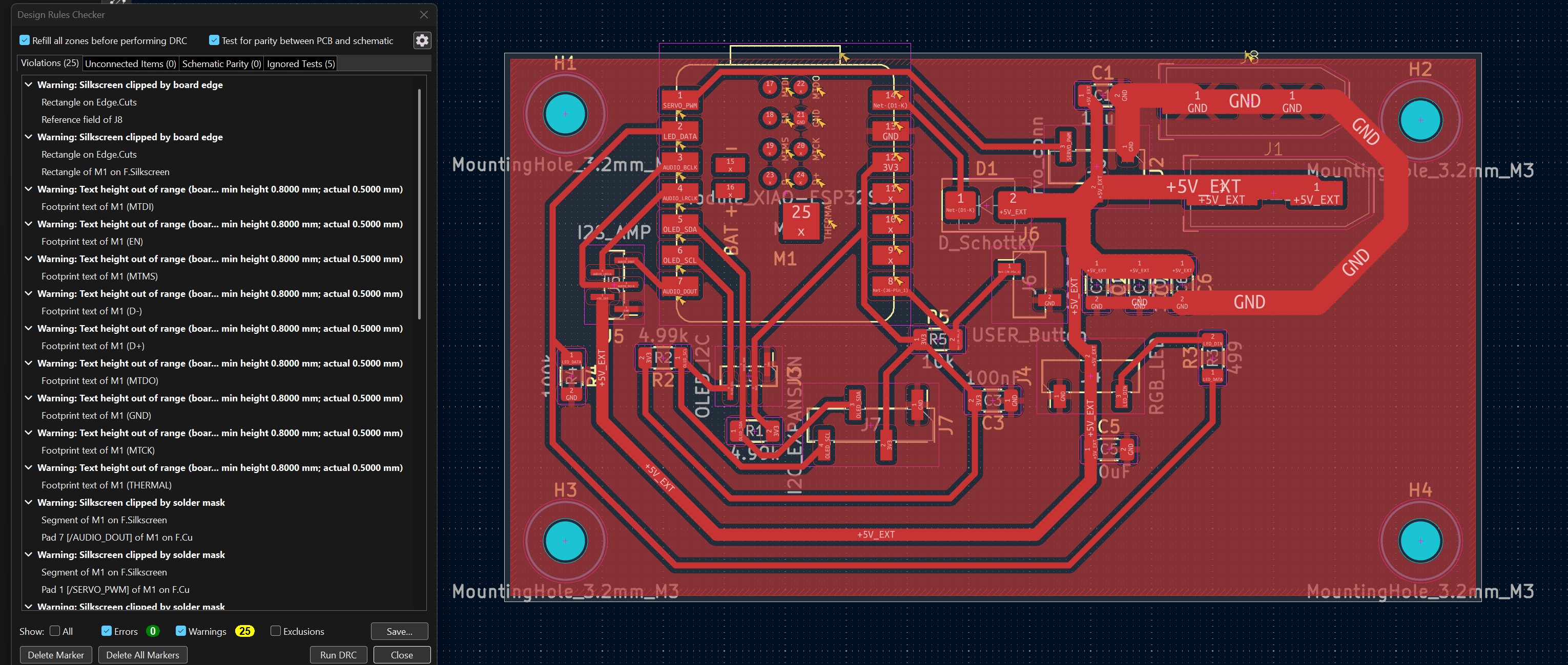
Revised board design
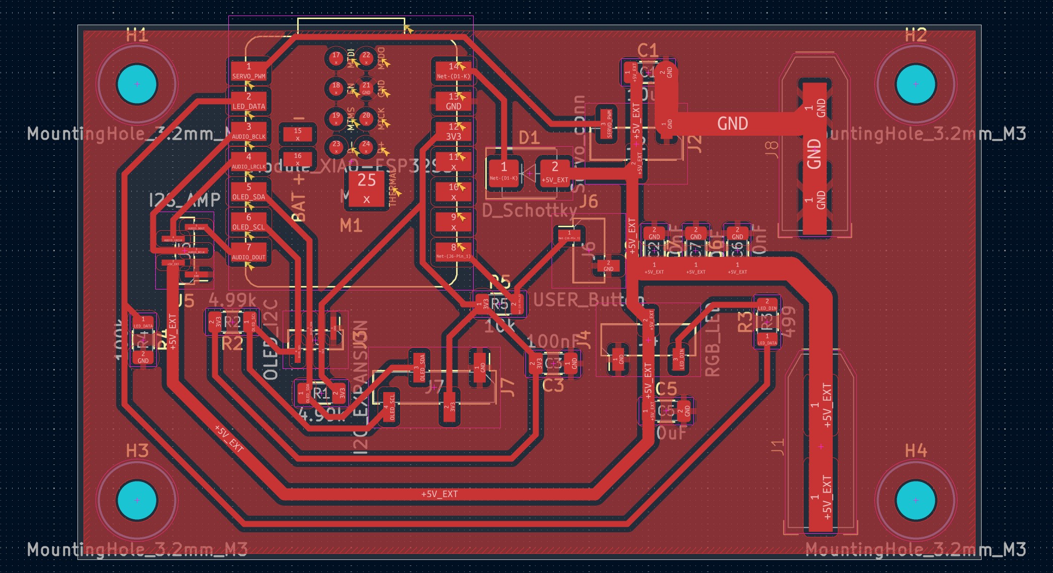
Revised board design. The removal of logic buffer also solved the previous separating ground issue. After some significant rewiring, I was able to remove the 0ohm resistors previously serving as jumper wires.

PCB Milling

I then proceeded to mill the board using the Bantam machine inside the EECS Lab.
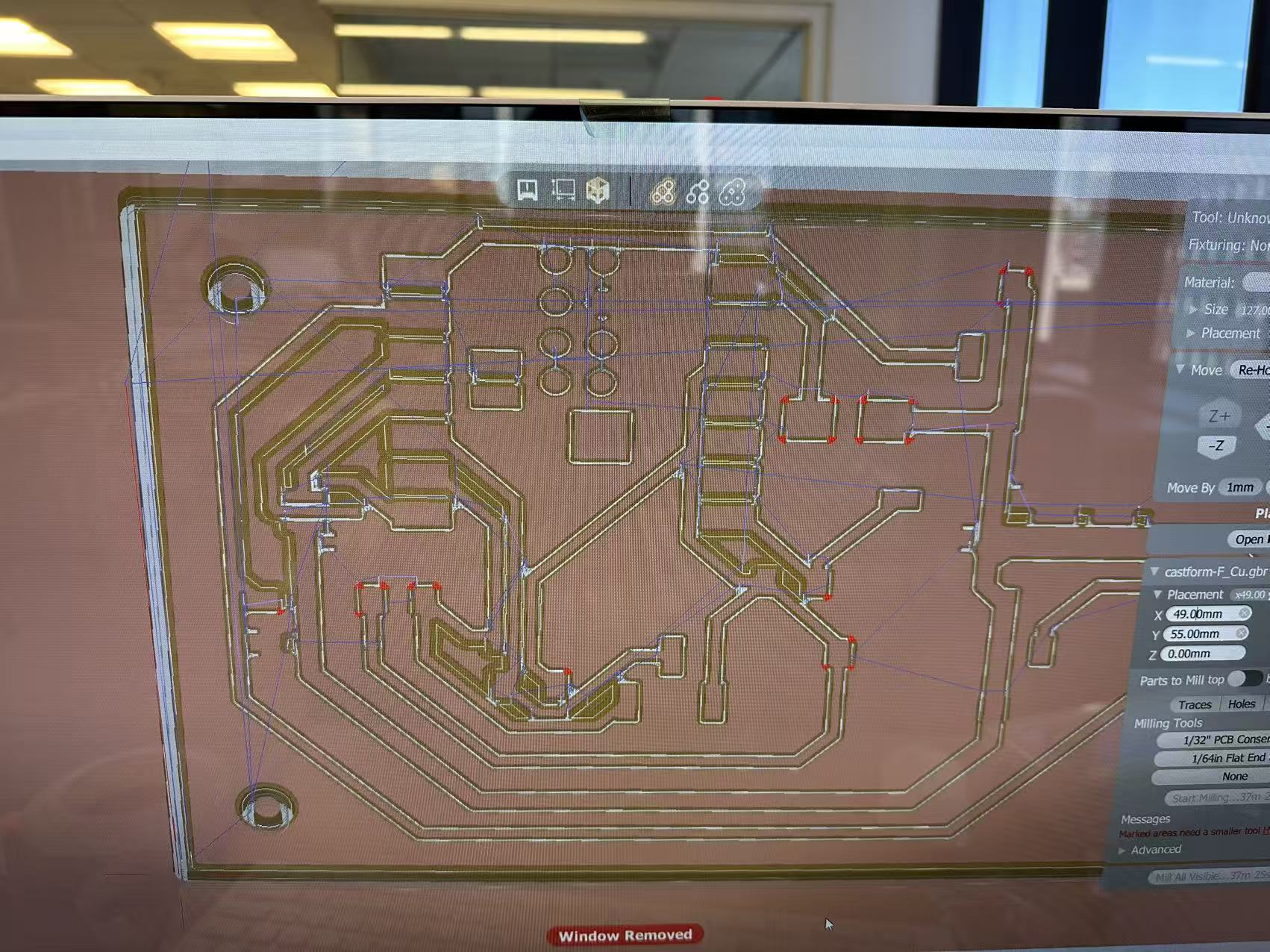
Milling tolerance issue
However, after I imported the gerber file into the Bantam machine, I found that the software prompted me it could not mill the regions marked in red above. Even with a 1/64inch end miller. Upon some inspection, I found out that it was because the 0.41mm clearance I used in my design was just under the limit so I went back to the design.
Revised and revised again board design
I ended up increasing the clearance to 0.45mm to resolve the issue. I also adjust the connector poisitons a little bit to make design more compact.
Milling software screen
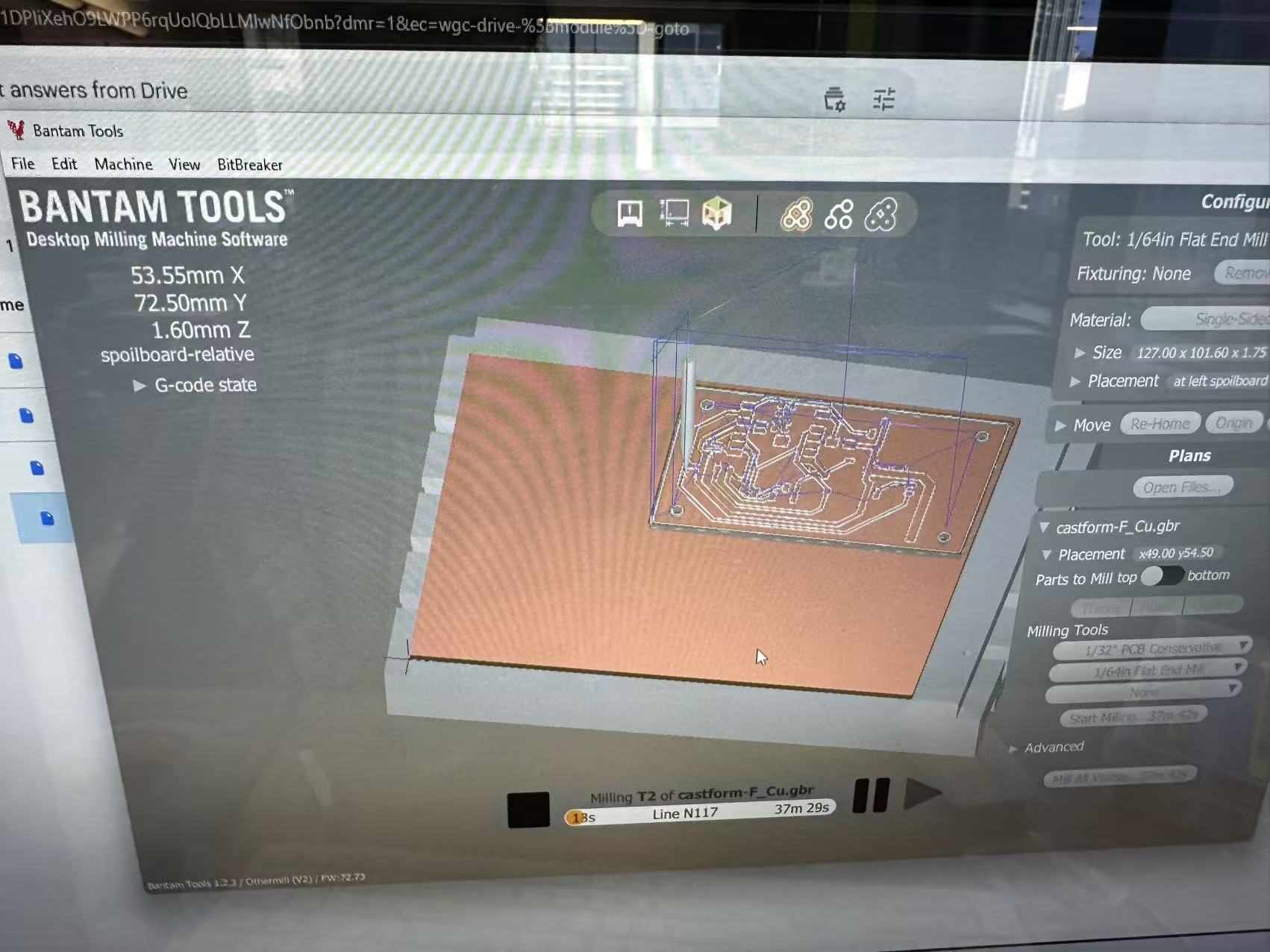
Milling Bantam machine software screenshot. This time there are no red parts.
Milling software screen
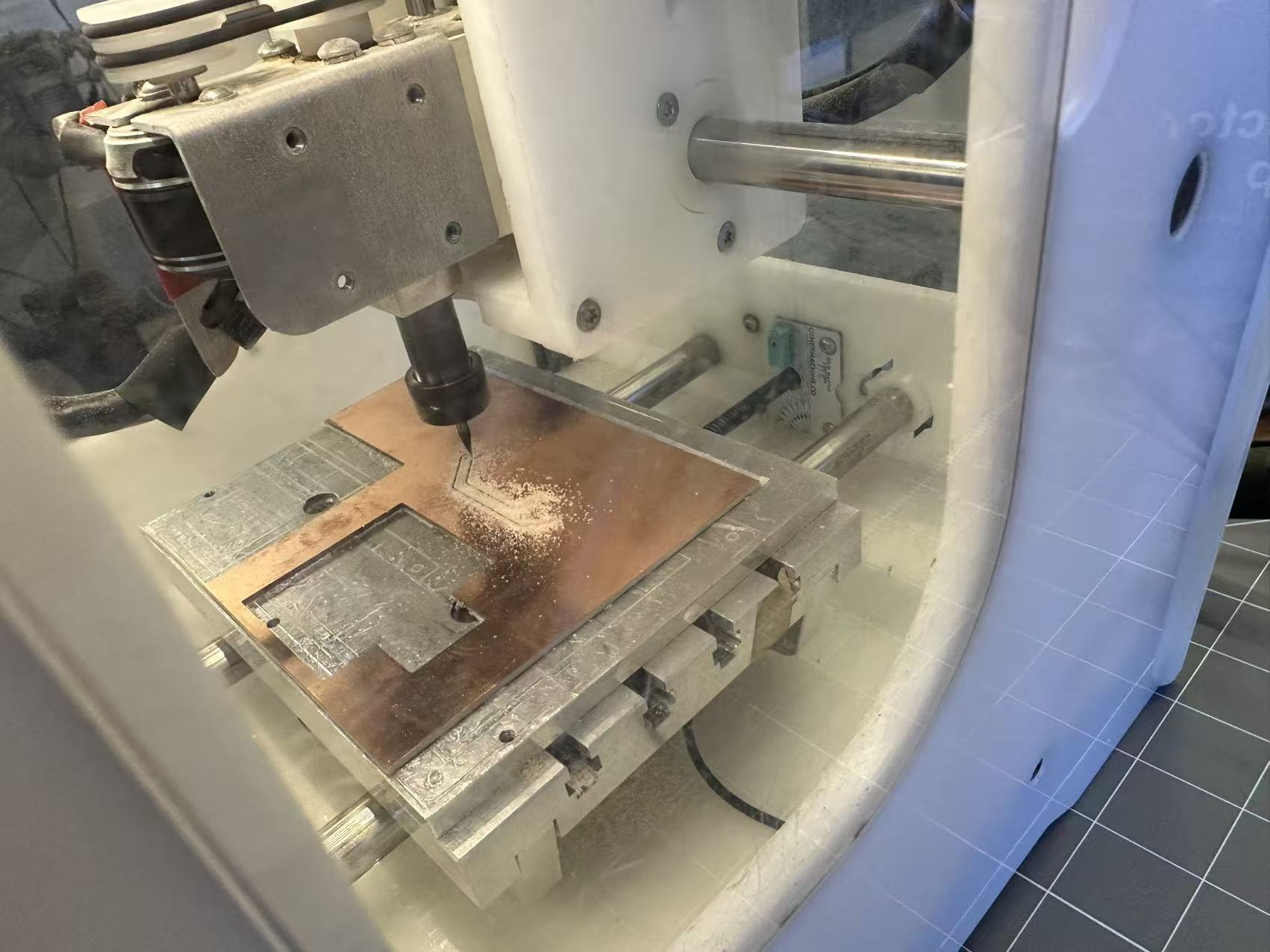
Board in middle of milling.
Milled board
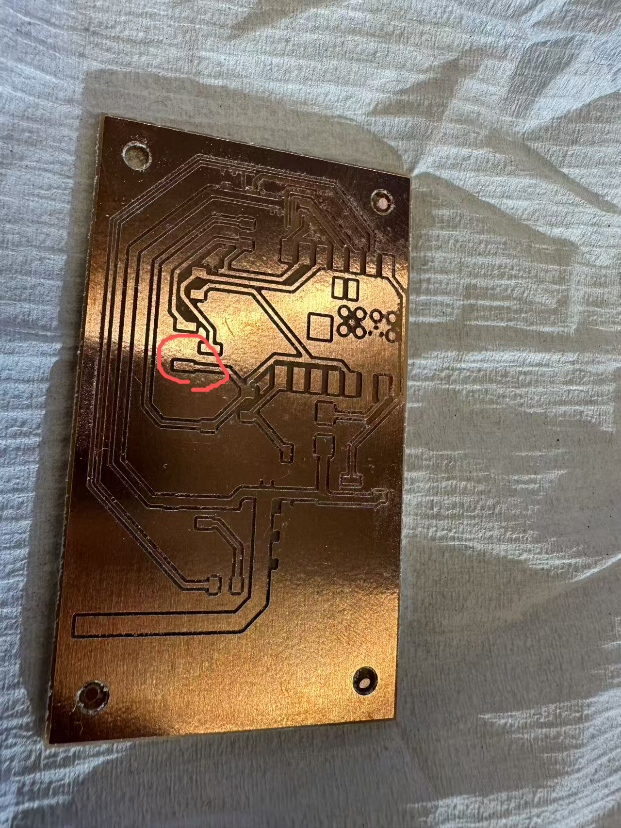
Milled board. After some testing, I found out there was a short between ground and my 3.3V connection. After some inspection under the microscope, I found out that the circled region had some copper debris that caused the short. I resolved the issue by manually cleanning the traces.

Board Soldering and Testing (Take 1)

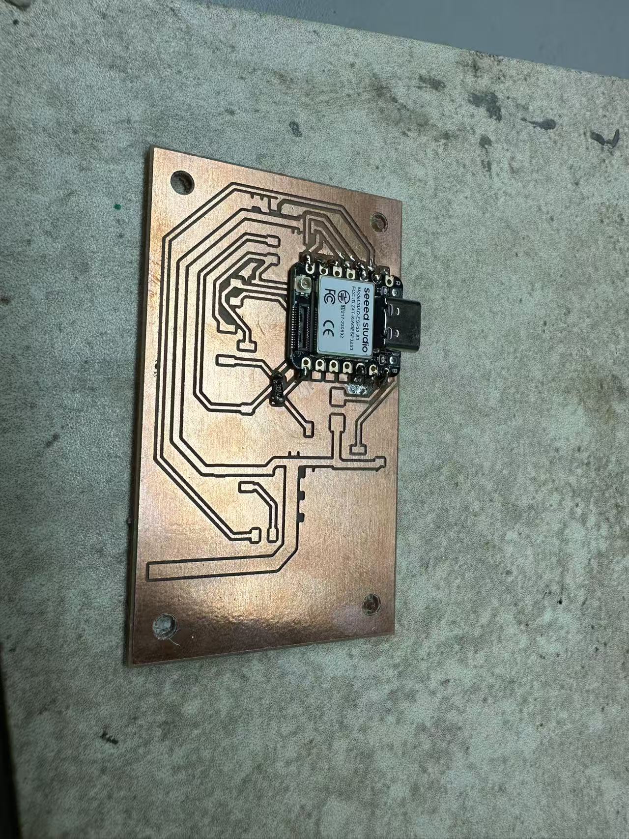
After the board was milled, I proceeded to solder the components on the board. Since I was a bit short on time after all the debugging, I decided to focus on the microcontroller part first.
Schematic revision
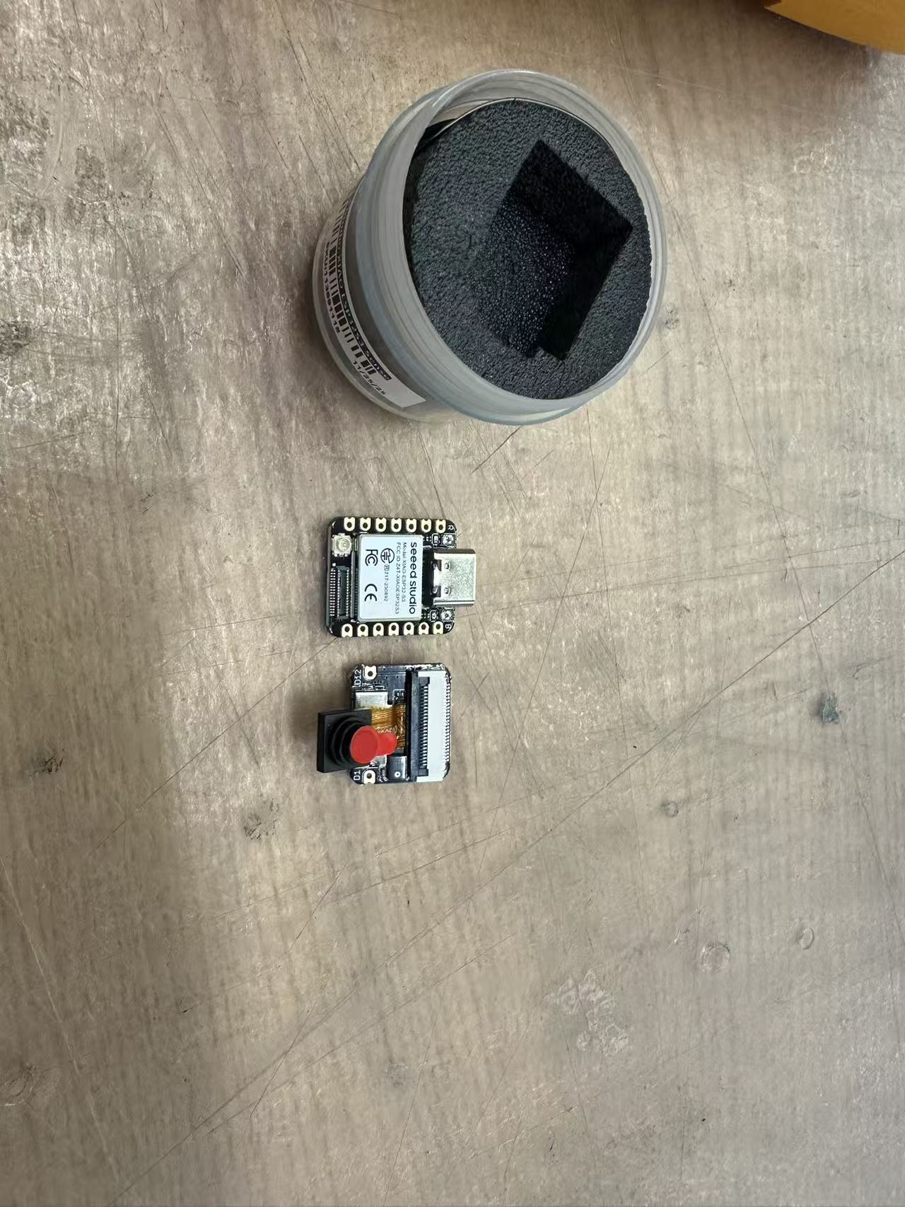
Per my design, I used a ESP32-S3 Sense Xiao board to support all my input and output needs.
Microcontroller soldered
Microcontroller soldered on board. I also ran into a short issue due to excessive lead on the right side of the microcontroller. I resolved the issue by removing the lead with braid.
Testing the mircocontroller with the Arduino built-in blink example. You can see in video that it's functioning as expected.

Next Steps