Week 4: Electronics Design
To be very honest, I was a bit intimidated by this assignment before starting it. I really do not have very much experience with circuits. After doing the QPAD assignment and this week's lecture and recitation, however, I was looking forward to it. Doing the assignment would finally give me the opportunity to sit down and learn some more about circuits. Still, this class's assignments with their pace and their breadth of material can be intimidating, so I worked closely with Claude from the get-go:
Some progress towards the final: Earth-field NMR "pulse programmer"
Okay well, I'm gonna have to get real nerdy here for a second to adequately explain this, but bear with me.
A general (but still rather superficial) description of NMR is available in my final project page. I will try my best to improve it a bit as the class goes on, but trying to explain NMR to a general audience has certainly pushed me to recognize parts of the theory I still don't fully grasp. Still, I try to give myself some slack — it's a new field for me! In any case, I'll be repeating some info here because it is also direct context for this week's assignment.
Polarization or magnetization is proportional to the magnetic field: the stronger the field, the more pointed along that axis the spins are. In the Griffin Group, we have many different magnets, and instead of referring to them in Gauss or Tesla, we refer to them according to the proton Larmor frequency at that magnetic field strength: \[ \omega_0 = \gamma B_0 \qquad \text{or} \qquad \nu_0 = \frac{\gamma}{2\pi} B_0 \] So, an 800 MHz magnet, for instance, corresponds to 18.8 Tesla. For better data, we typically try to use the 800 MHz as increasing the field strength is usually an NMR spectroscopist's "get out of jail free card" in a lot of situations, and the 800 MHz is our strongest working magnet.
Now, the 800 MHz is the size of an SUV and has a superconducting coil kept at around 4 K by eye-watering amounts of liquid nitrogen and liquid helium. 18.8 Tesla is, after all, 376,000x stronger than Earth's magnetic field (~50 mT). So, it goes without saying I cannot try to replicate those experimental conditions for my final project. To do NMR from scratch, then, I have to get a bit creative. Here's the part where I'll have to get a little technical. At high fields, like the ones in our lab, a measurement is collected by pulsing the spins with a radio-frequency (RF) pulse that perturbs the spin away from their equilibrium aligned with the field axis (the z-axis) by 90°, putting them on the xy plane. As these spins relax back to their aligned, equilibrium position, a coil measures the transverse magnetization (i.e "how much the spins point" in the xy plane), resulting in the decaying sinusodial data shown in my home page (the free induction decay or FID). We then Fourier transform the FID to obtain discrete frequencies.
For earth-field NMR, I cannot take this approach. The pulse is very doable, actually, but that is not necessarily the problem. The RF pulse would be on the order of ~2 kHz, which is audio frequency, so the Xiao could generate the waveform directly and a simple audio amplifier could drive a small coil. As mentioned before though, a lot of things in NMR scale with the field. In this case, the relevant thing is thermal polarization. At 50 μT, the polarization along the earth-field is very small to begin with. Assume I'll measure a few hundred mL of water. In this liquid, all the spins point everywhere, but due to the small field, some more spins will point "north" than "south." I can then pulse 90°, and all the spins will flip coherently, but that magnetization will still be small, and our signal will therefore be tiny (if at all observable).
How do I get around this? Instead of pulsing, I will take a different approach (one which will even facilitate the circuit design). I will polarize the spins perpendicularly to the earth-field (which is what would happen after a 90° pulse anyway in a typical experiment, where they are initially polarized about the z-axis) to begin with. Then, I will turn the field off very fast, and the spins will precess until they decohere, like they would with a regular pulse, only that the magnetization will be a few hundred times larger to begin with now, allowing me to get more signal with less scans.
Jesus, that took a lot of asking Claude for analogies. I need to read up on my spin dynamics. If I can't explain it, I don't know it well enough!
In any case, I was flirting with the idea of doing something like this to start making some progress on my final project. Actually, I wanted to do the same thing but with direct RF pulsing, and instead of earth-field, driving my own magnetic field by running current through a coil. Claude actually suggested this specific earth-field idea since I had been asking it logistical questions about my final project. For simplicity, I am going with this earth-field thing for now, because now that I learned how to design embedded systems, I think adding all this extra stuff later will be easily doable. Time will tell how ambitious I end up being.
Choosing Parts
| Circuit Component | Part | Role in the Experiment | Why |
|---|---|---|---|
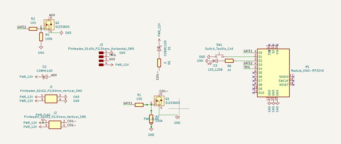
| Microcontroller (M1) | Seeed Xiao RP2040 | Runs precise timing sequences ("the conductor") | Programmable, precise timing (μs); 3.3 V enough to switch MOSFETS |
| Coil switch (Q1, Q2) | SI2336DS N-MOSFET | Lets the Xiao turn coil current on and off to polarize sample | Fully on at 3.3 V (logic); low on-resistance (~46 mΩ); rated for 30 V / 4.3 A which covers the coil |
| Flyback diodes (D1, D2) | CDBM1100 Schottky | Absorbs the coil's switch-off spike | Faraday/Lenz Laws: coil resists sudden current drop and spikes voltage; D1 lets that current circulate and decay safely |
| Gate Resistors (R1, R2) | 100 Ω | Sits between Xiao and transistor gate | Limits current spike into gate when current is turned on |
| Gate pull-downs (R3, R4) | 100 kΩ | Holds transistor gate at ground when Xiao not driving it | Keeps coil off during boot or reset so it does not accidentally turn on |
| LED + Resistor (D3 + R6) | LED + 1 kΩ | Shows coil is on | Visual cue that current is flowing; R6 limits LED current |
| MOSFET/Diode Resistor (R5) | 0 Ω | In series with D1; determines how fast the current decay is | 0 Ω placeholder; increasing it will lead to faster switch-off but 12V + IR5 should be below 30 V |
| 2X2 Headers (J1, J2) | Connectors | Bring in external 12 V supply to power the coil; connect polarizing coil between 12 V and COIL- | Pins are doubled (1 & 3 are 12 V, 2 & 4 are GND/COIL- so current is shared across two pins |
| 1x4 Header (J3) | Connector | Carries GND, TRIG, AUX, and 12 V to other equipment | Connecting pulsing and experimental set up to measurement part (to come in a later board) |
Schematic
The schematic is given above. What this circuit is essentially doing is the following:
(1) You press the switch/button hooked up to pin D1 and the Xiao starts a measurement. (2) Later, with programming, the Xiao sets D0 to high, turning on Q1 (the MOSFET). 12 V drive current through the coil (J2) for a programmed time. (3) After this time, D0 is set to low, turning off Q1, and the current decays through diode D1 and R5. (4) When the pulse is switched off, D4 pulses on J3 to tell a data recorder (more on that in coming weeks) to start capturing the FID. (5) A second MOSFET (Q2), switched by D3, provides a spare 12 V output (AUX on J3). I plan to use it to protect the receiver: a relay will keep it disconnected until the switch-off spike has passed.
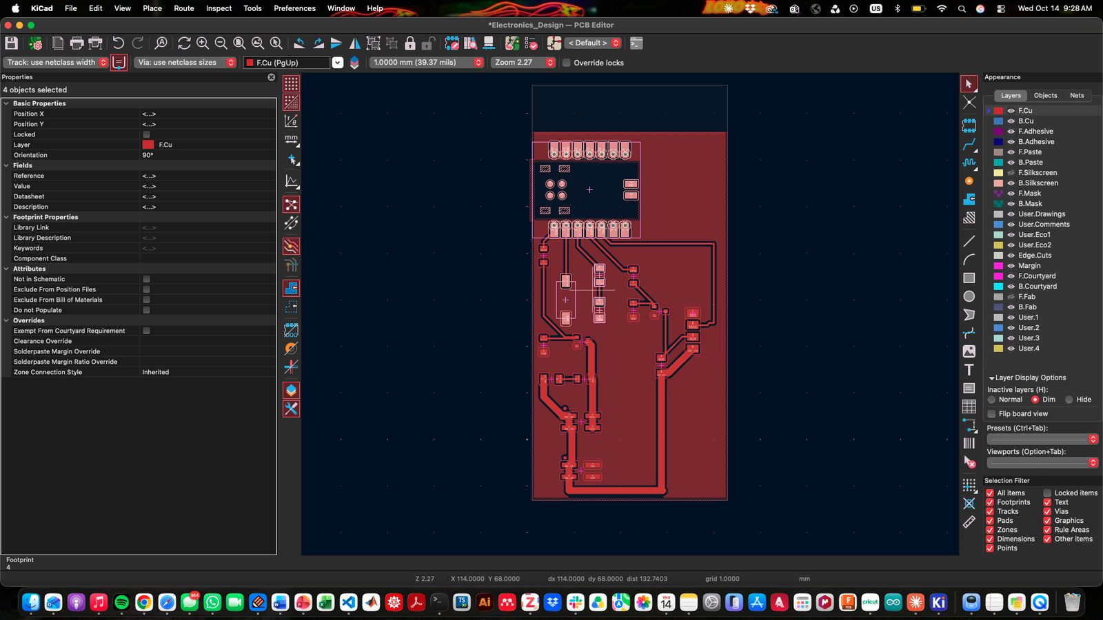
Board layout
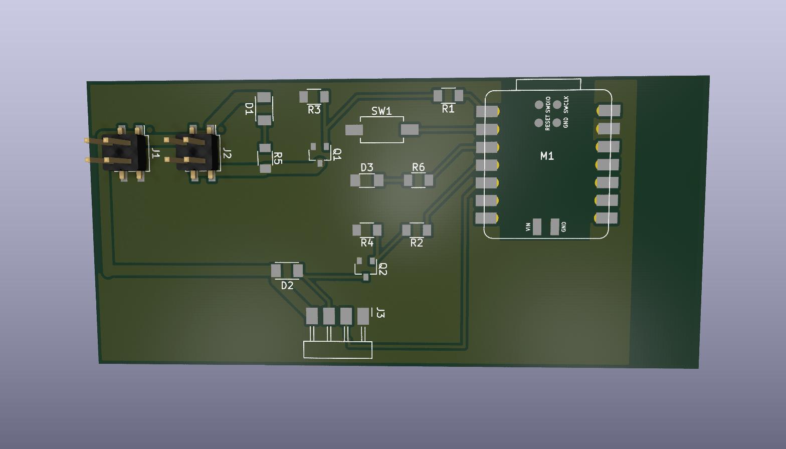
Here, I would love to go into detail as to how I did this, but I just sort of arranged and rearranged stuff until my connections were clean and there were no wires crossed. The only real consideration was ensuring that the "wires" were thicker for the parts of the circuit which deliver power to and from the coil, and the logic connections were much thinner. This was done by creating a separate net class for the 12 V, coil, and ground nets with wider traces (File --> Board Setup --> Net Classes).
Also, something worth mentioning is that, from the PCB design, I had to change the wirings on the schematic so that the board layout would not be nightmarish. I don't recall exactly what it was, but I think I just changed which Xiao pins prompted what, nothing extraordinary. It did result, however, in a much more straightforward board arrangement.
Design rule check
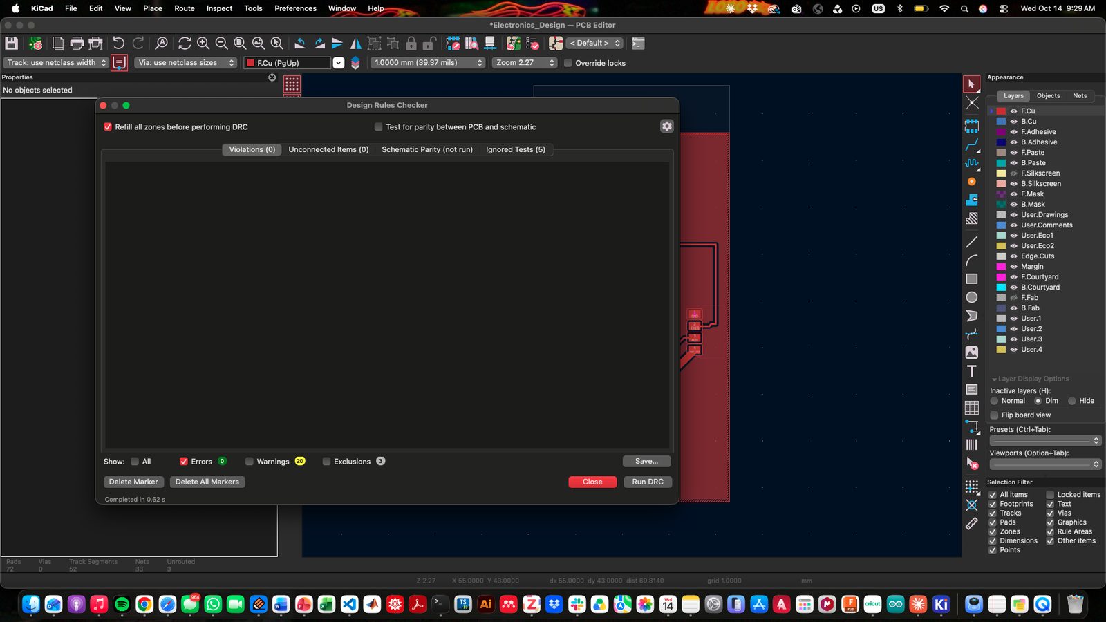
| Rule | Value (mm) |
|---|---|
| Minimum track width | 0.4 |
| Copper-to-board-edge clearance | 0.5 |
| Hole clearance / hole-to-hole | 0.25 |
| Minimum via diameter / through-hole | 0.5 / 0.3 |
| Class | Track width (mm) | Clearance (mm) | Nets |
|---|---|---|---|
| Default | 0.4 | 0.4 | Everything else: GATE1/2, TRIG, AUX, LED, button |
| Power | 1.5 | 0.4 | PWR_12V and COIL− (assigned by the patterns *PWR_12V* and *COIL-*) |
3D view
AI Documentation
To see my AI usage, please see here.