Week 5
ELECTRONICS DESIGN
Necessary Components
For my final project, the remote mahjong table, we can break down the machine into multiple components: identification, PUT tile, GET tile, and dispensing, wireless communication.
This week, I decided to focus on the tile movement/categorization part first since I’m not set on the mode of identification yet. I think I need a motor for the magnetic belt, an array of IR-sensors for tracking when the mahjong tile is at the correct position, and a switch to turn the table on. I wasn’t quite sure which motor or what the array is going to look like yet, so I started off with 2 connectors to signify the magnetic belt and IR-sensor arrays. I also added a switch to turn it on and an LED to display the status.
| Component | Description | Purpose |
|---|---|---|
| XIAO ESP32-C3 | Wi-Fi-enabled microcontroller | Main controller and wireless communication |
| S1 | Switch | Manual control input |
| LED | Indicator LED | Visual feedback |
| R1 | Current-limiting resistor | Limits current through the LED |
| R2 | 0 Ω resistor | Jumper connecting 3V3 to J2 pin 3, allowing a trace to cross underneath |
| J1 | 2×3 pin connector | External motor-driver interface |
| J2 | 2×3 pin connector | Future tile-identification interface |
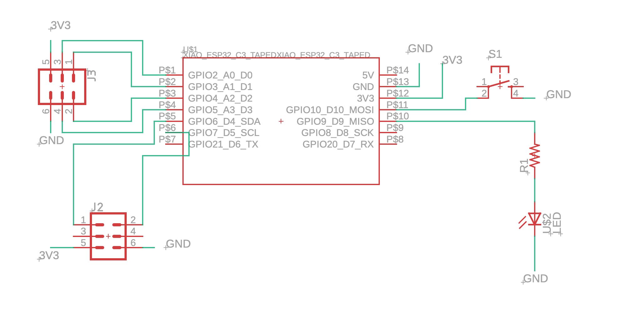
Initial Schematic
Microcontroller Pin Assignments
| XIAO Pin | GPIO | Connection |
|---|---|---|
| D0 | GPIO2 | J1 pin 4 |
| D1 | GPIO3 | J1 pin 6 |
| D2 | GPIO4 | J2 pin 2 |
| D3 | GPIO5 | J2 pin 4 |
| D4 | GPIO6 | Unused |
| D5 | GPIO7 | Unused |
| D6 | GPIO21 | Unused |
| D7 | GPIO20 | Unused |
| D8 | GPIO8 | Unused |
| D9 | GPIO9 | LED through R1 |
| D10 | GPIO10 | Switch |
| 3V3 | — | J1 pin 2, J2 pin 3 through R2 |
| GND | — | J1 pin 1, J2 pin 1, LED, switch |
| 5V | — | Unused |
J1 Pin 3 and 5 and J2 pin 5 and 6 are left open for connecting to external peripherals (motor and IR-sensor array module respectively). Additionally, GPIO 6, 7, 8, 20, and 21 are also open if I want to add connections to more modules.
Final Schematic and PCB
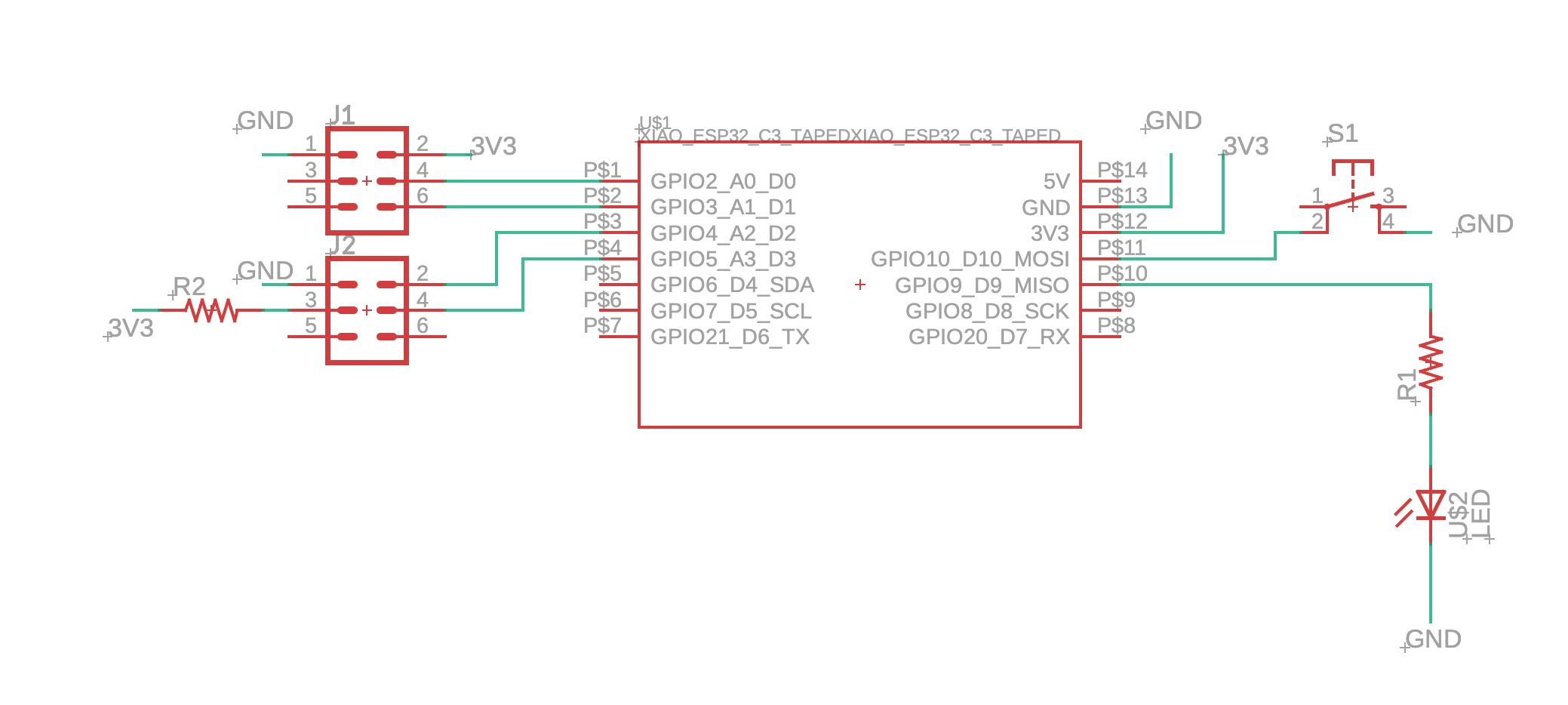
As I anticipated, the initial schematic resulted in crossing wires for the 3V3 and GND and I tried out a couple orientations, but decided a resistor jumper is the easiest solution. I added the resistor jumper with it set to 0k-Ohms and this allowed the wires to be connected properly.
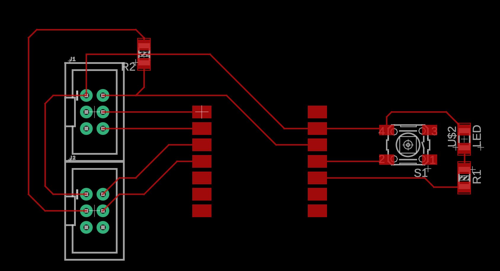
Here is my final PCB design! It passed the design rule checker when I ran it so fingers crossed it is all good.