

Week 6
ELECTRONICS PRODUCTION
My final project has a component requiring multiple server motors to work 1 by 1 so I decided to focus on this component for this week. It doesn’t require the flashiest circuit design, but is a crucial component for my project.
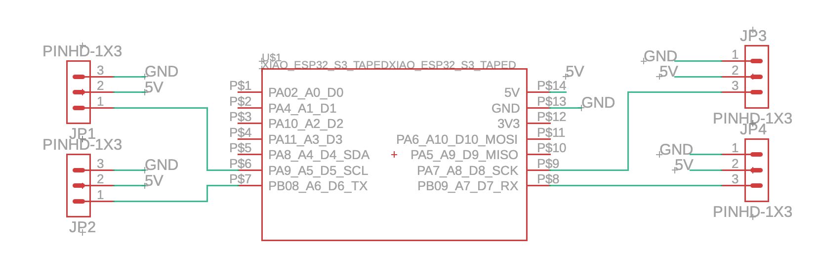
I had originally not connected the 5V to the XIAO ESP32-S3’s 5V pin because I got juked by an old online forum saying that you shouldn’t connect it to the 5V pin bc a microUSB / USB-A can’t provide enough power for it so my first-iteration board was only power-able by the bench power supply. After chatting with Anthony, I learned that this is no longer a problem for USB-Cs. Thus, in my final iteration, it should be powered by USB-C connected to my XIAO. However, I anticipate that my final project can’t be powered by USB-C once I add my other components so I expect this to be changed in the future.
Here’s the final PCB design:
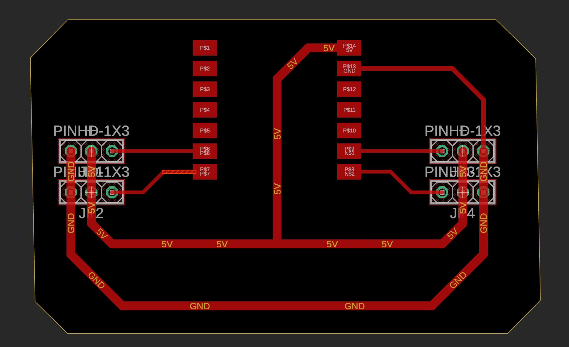
The milling process itself went pretty smooth, but not so much at the soldering stage. First, I had just used the copper plate that was already in the machine when I cut my PCB so I did not realize I accidentally used double-sided PCB when I cut it. Thus, when it came time to solder on my headers, I realized they’re all connected through the back… I also mesed up on the soldering p badly to begin with:
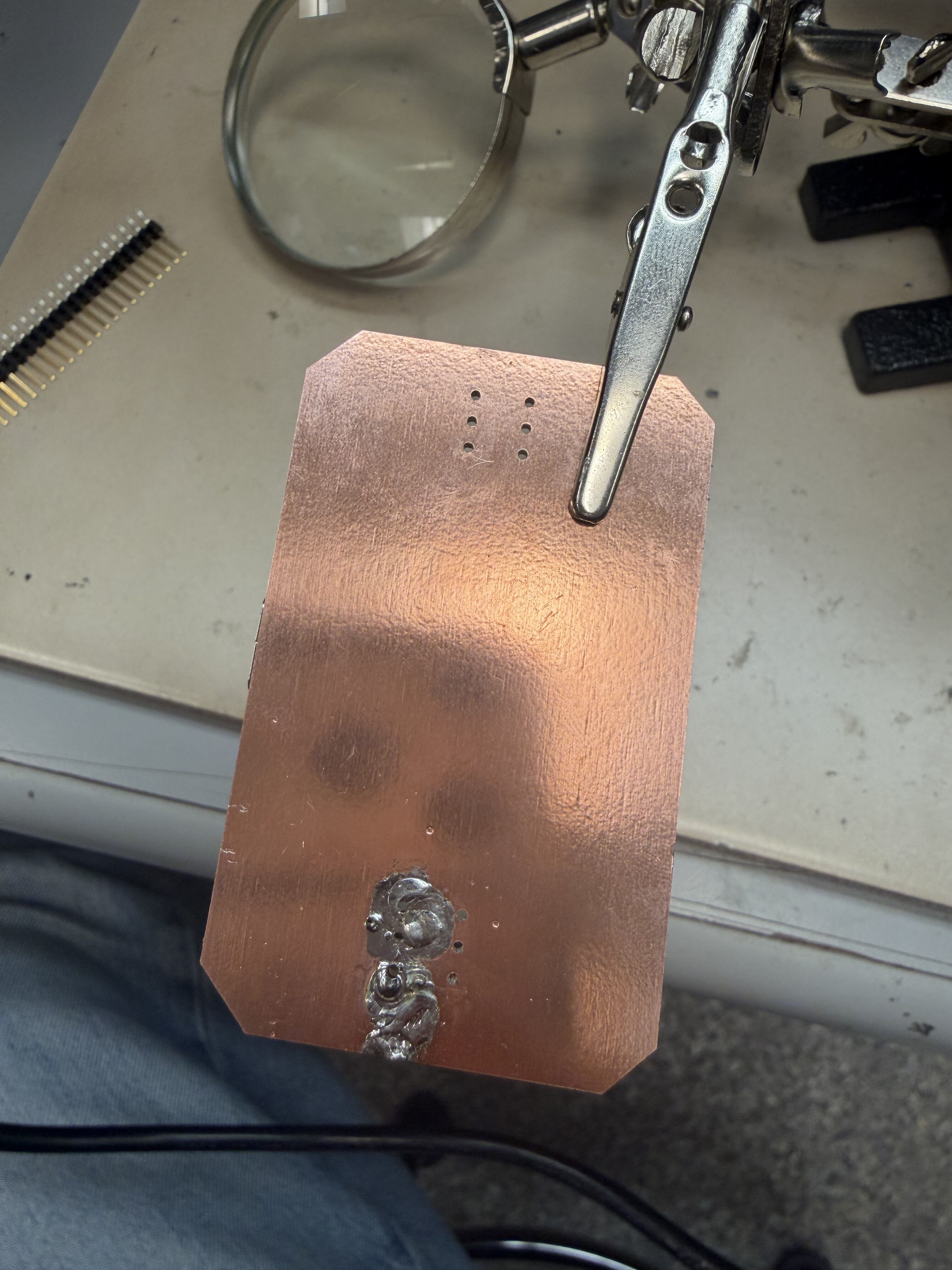
So, I used an ultrasonic knife to separate the PTHs on the backside and used the multimeter to test continuity and ensuring that my 5V and GND wouldn’t be shorted. Lastly, I used a power supply from the electronics bench to power my board. I hope you appreciate my jank servo holding setup (I am actually making a rig for this)