Test equipment
We started by checking signals with the measuring devices in the lab, first the Rigol DS1054Z oscilloscope.
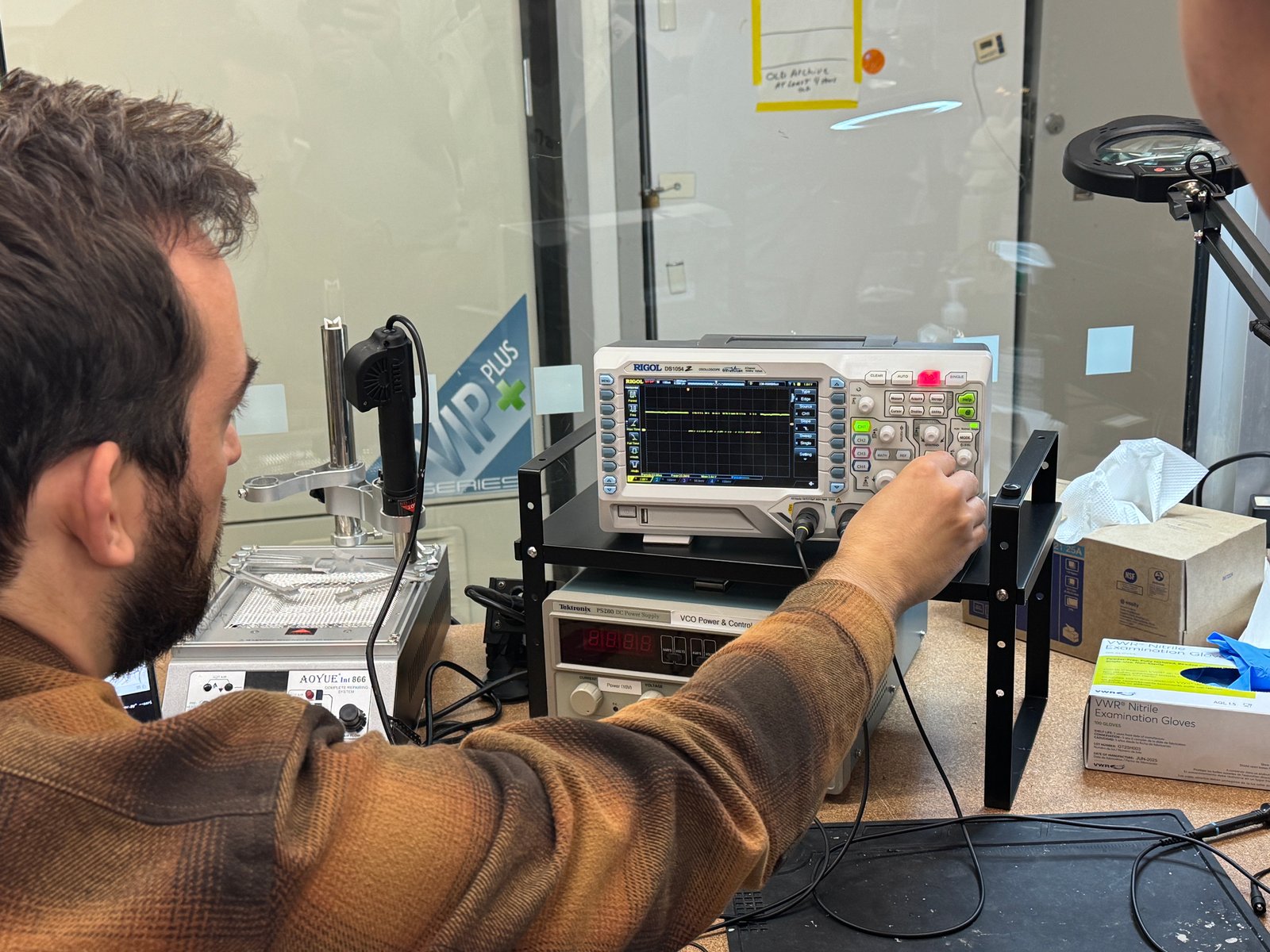
Then we adjusted the scope settings on its touch screen.
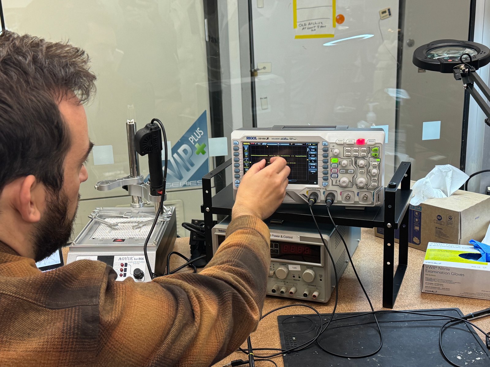
With the RS232 decoder at 115200 baud, the scope reads the serial message: h e l l o CR LF.
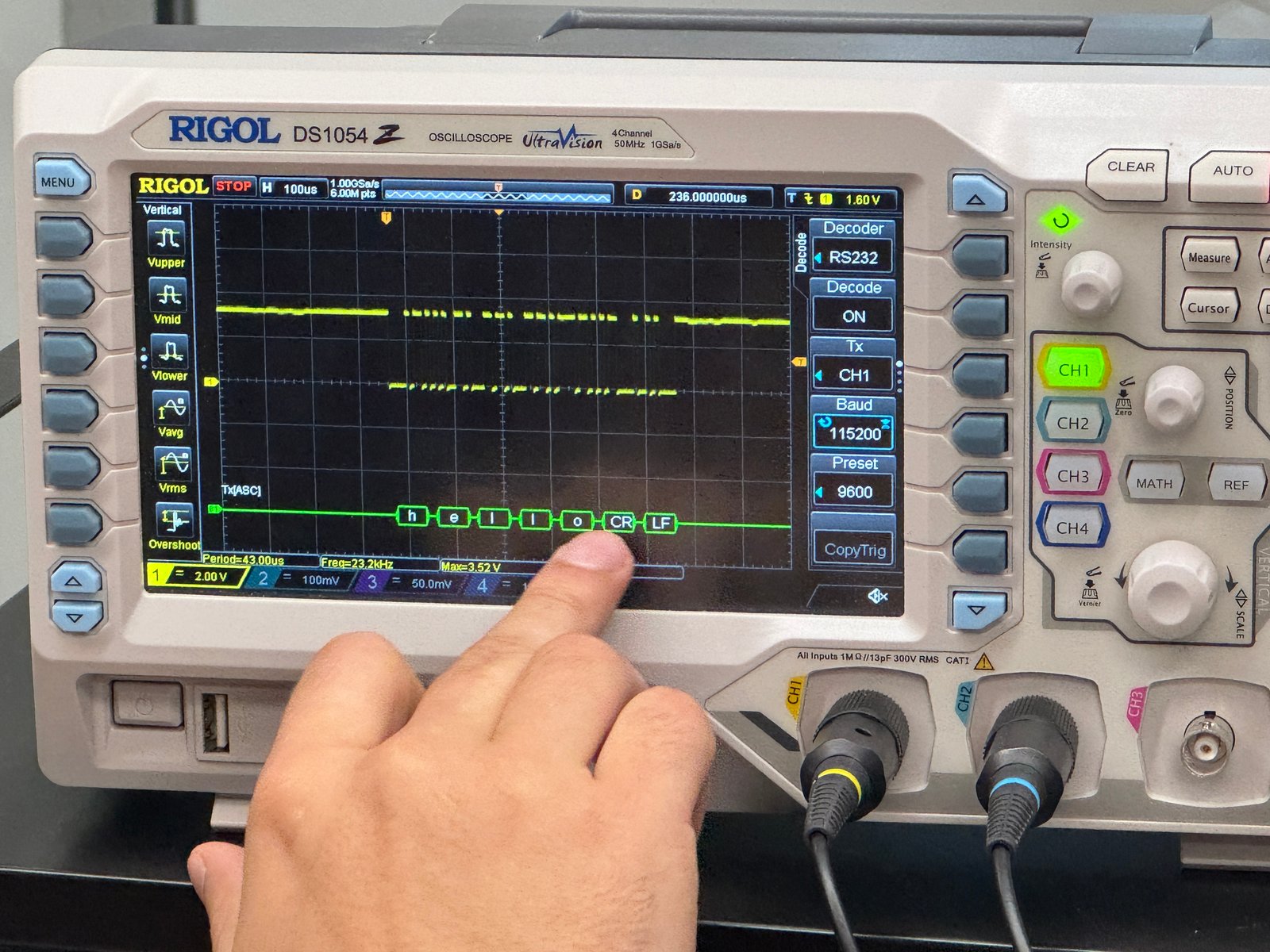
The same "hello" on the logic analyzer, decoded with its Async Serial analyzer.
KiCad (init-test_v1)
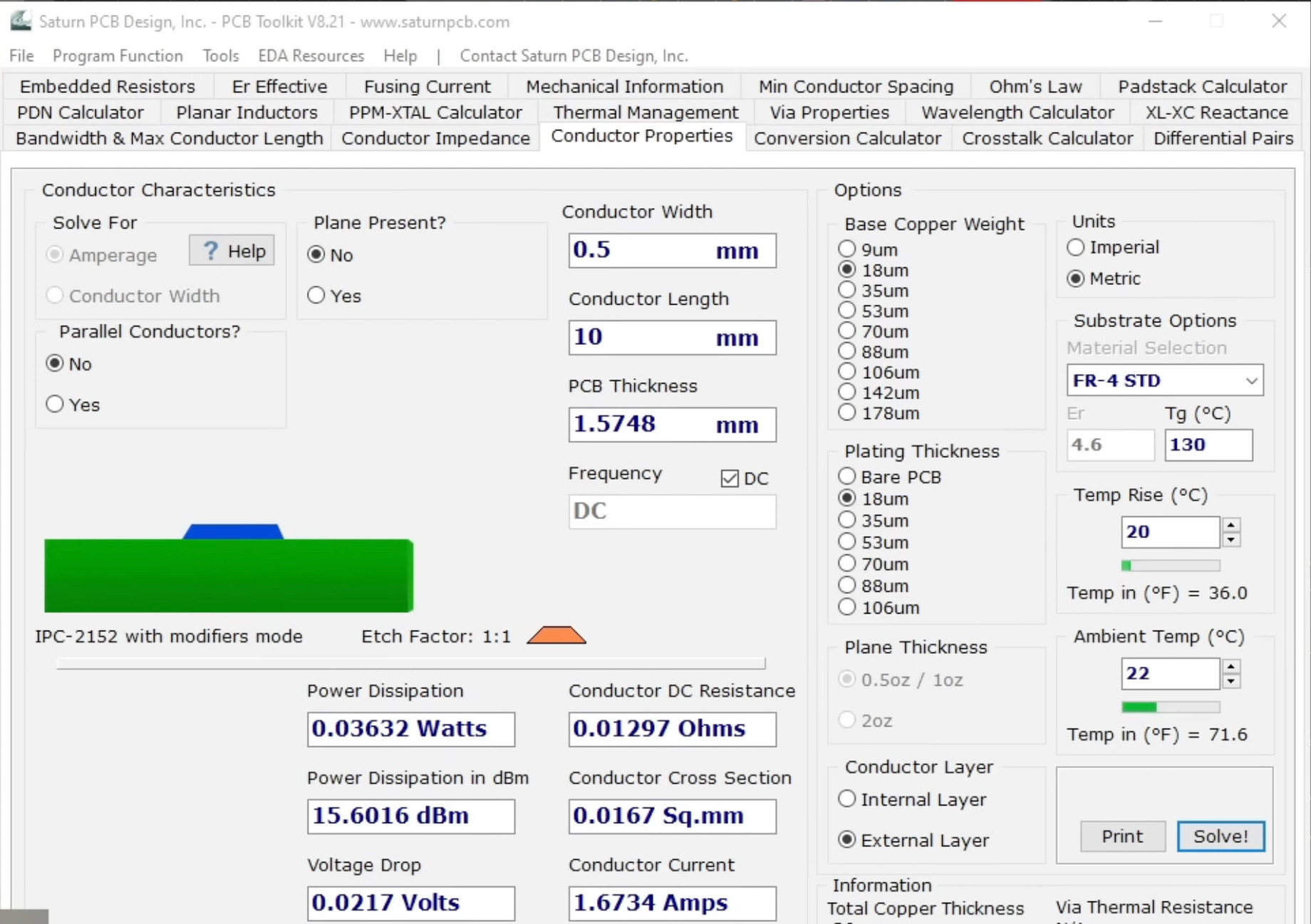
Before starting, I checked trace width vs. current (ref: Altium Academy): a 0.5 mm trace on 18 µm copper carries ~1.7 A at a 20 °C rise.
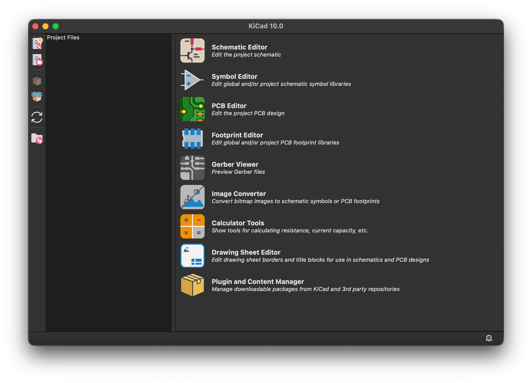
I started a fresh project in KiCad 10.
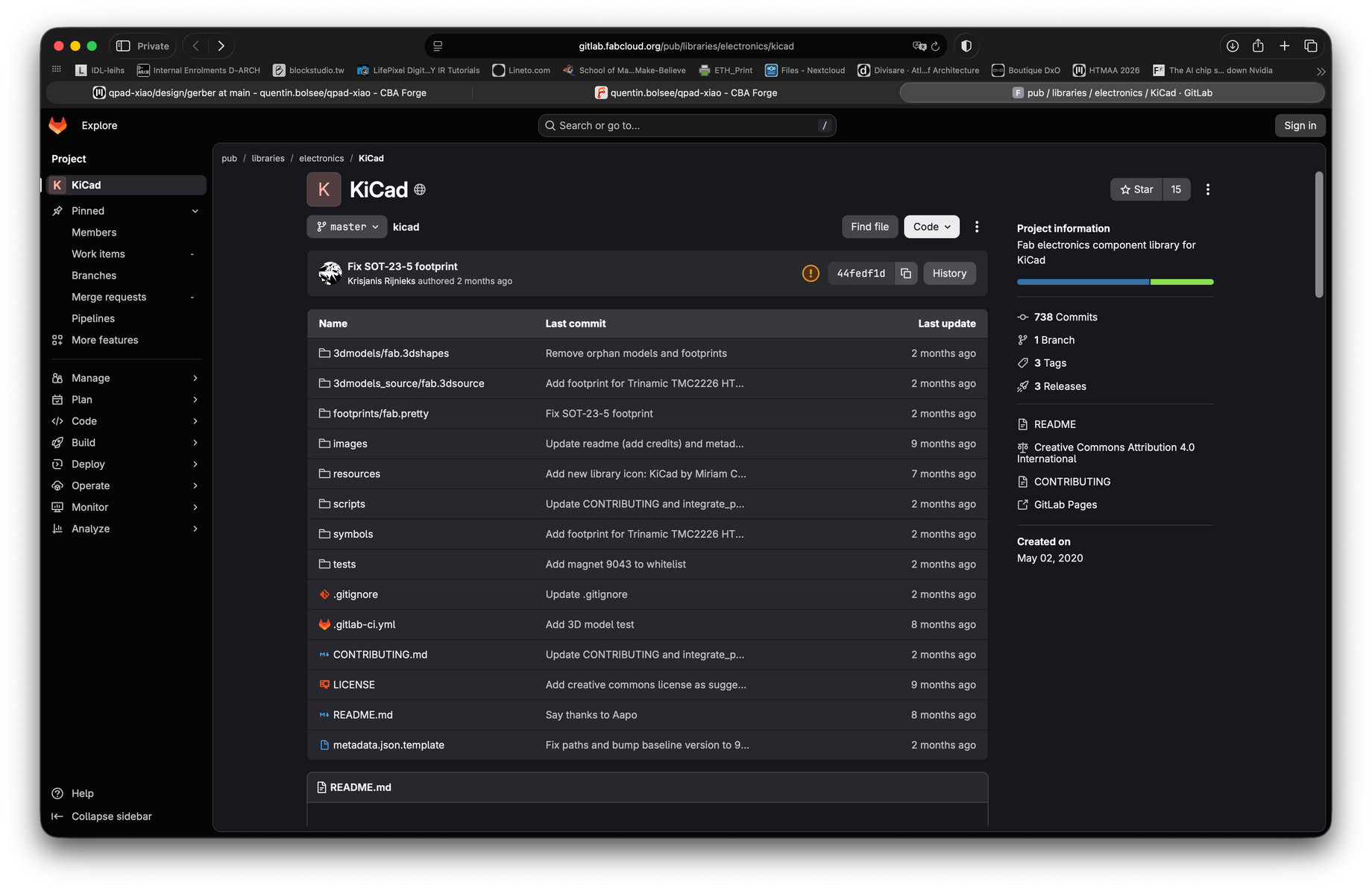
To get the parts we have in the lab, I added the Fab electronics library for KiCad from the fabcloud GitLab.
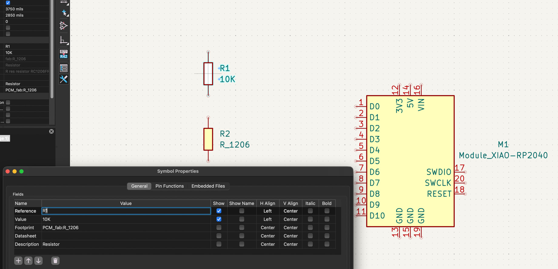
I placed the XIAO RP2040 and a 1206 resistor, and set its value to 10K in the symbol properties.
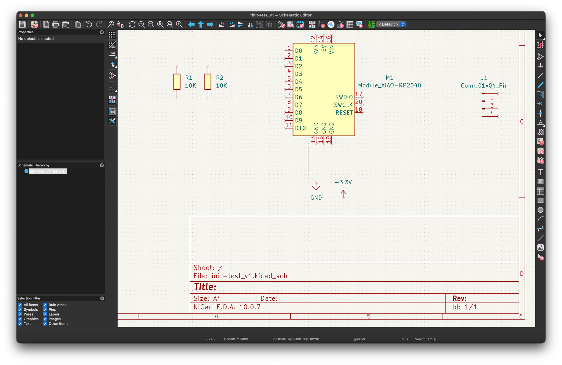
Initial placement: XIAO RP2040, two 10K resistors, a 4-pin connector, GND and +3.3V.
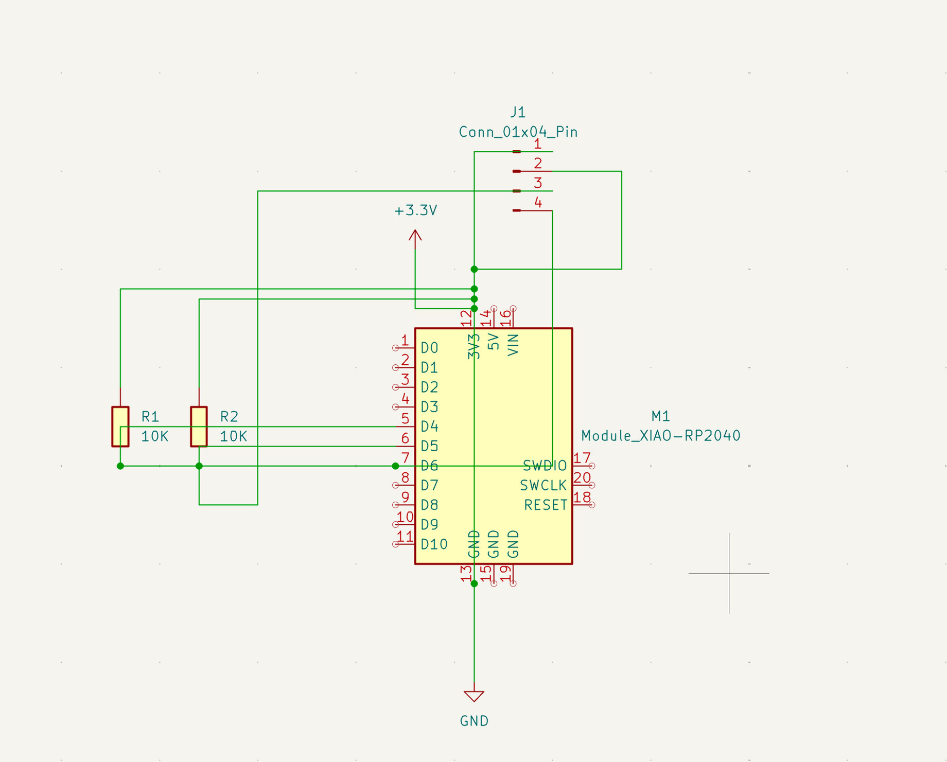
My first (horrible) attempt at wiring everything together.
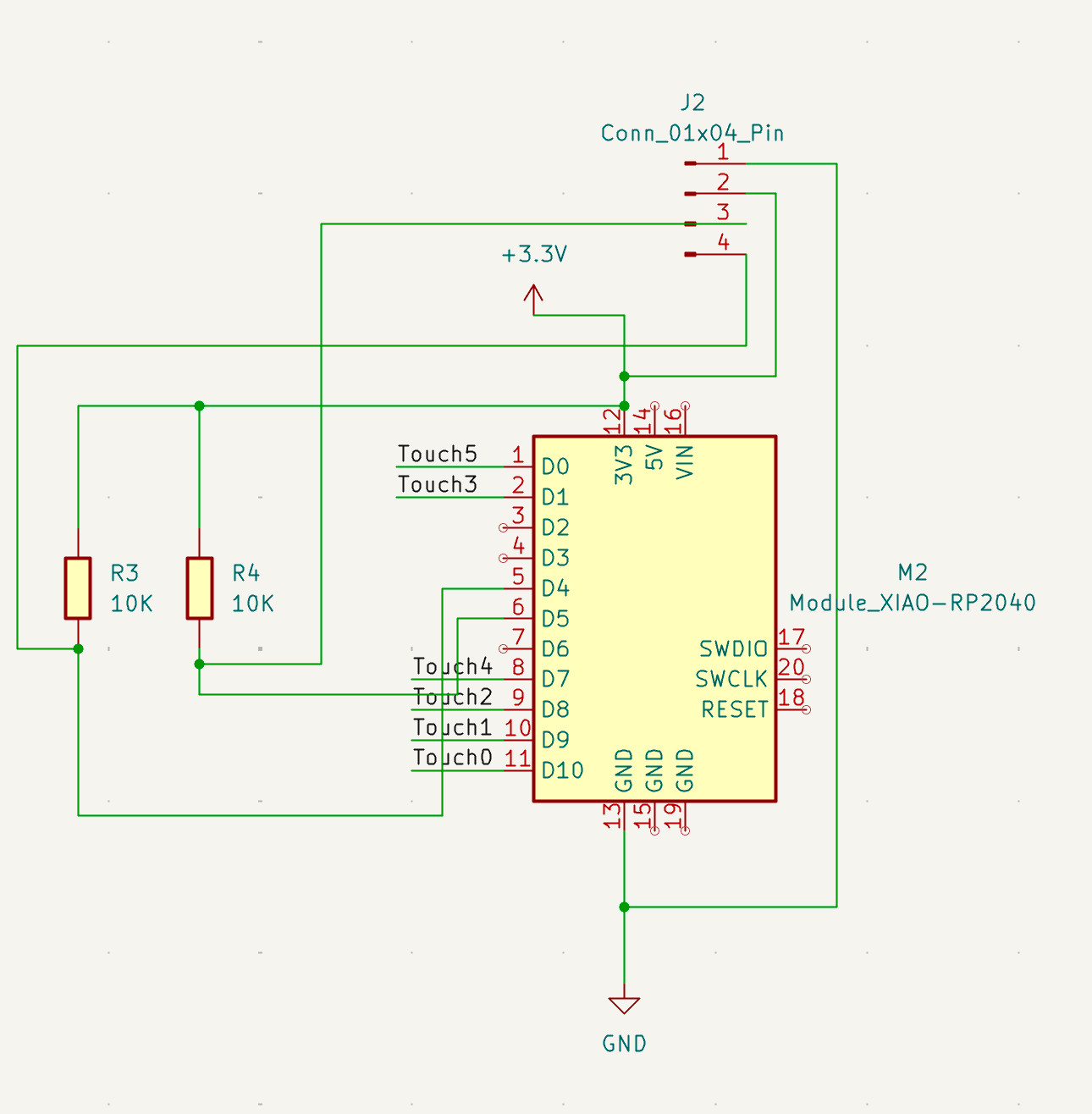
The second attempt is a lot cleaner, with labels for the six touch pins (Touch0–Touch5).
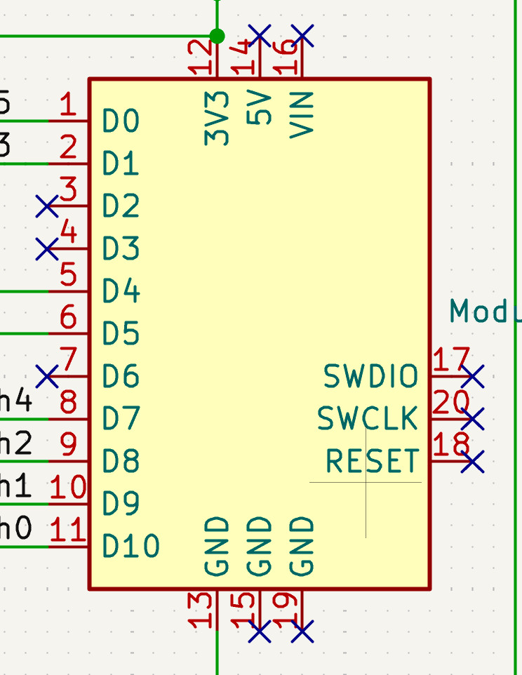
I marked all the unused pins as no-connect.
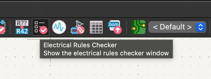
Then I ran the Electrical Rules Checker.
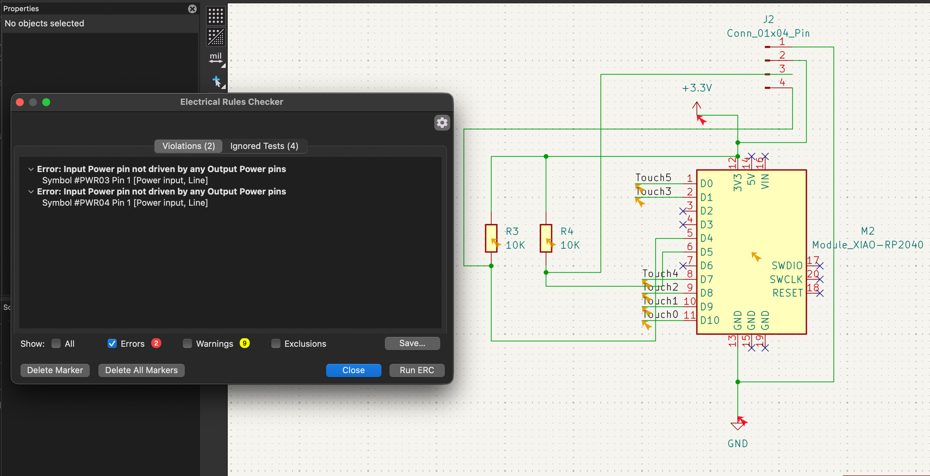
First major errors: the +3.3V and GND power inputs weren't driven by any power output.
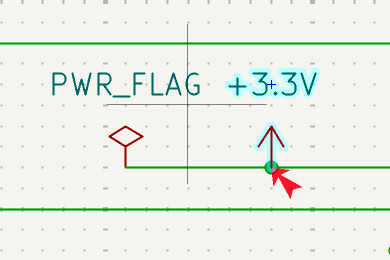
Adding a PWR_FLAG to the power net fixed it.
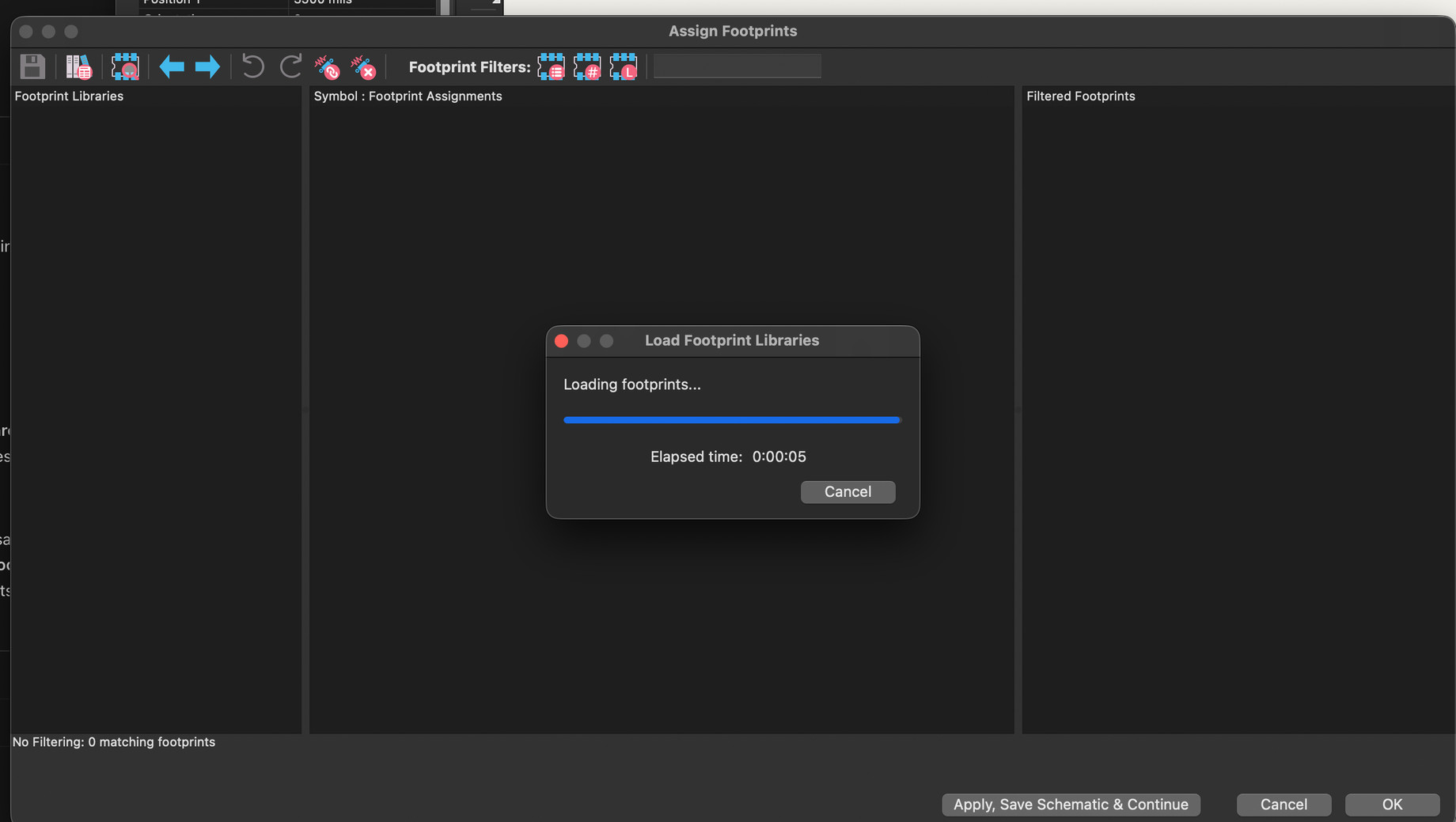
Next, assigning footprints (waiting for the footprint libraries to load).
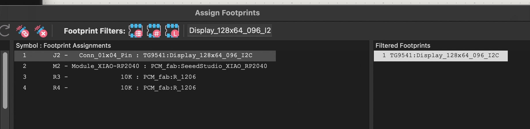
The fab library has no footprint for the 0.96" 128×64 I2C display, so I used TG9541's Display_128x64_096_I2C.
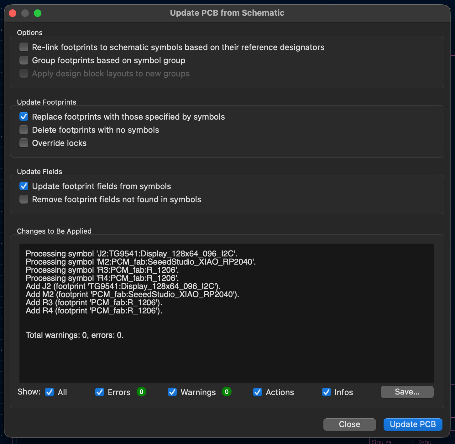
Updating the PCB from the schematic added all four footprints with 0 warnings and 0 errors.
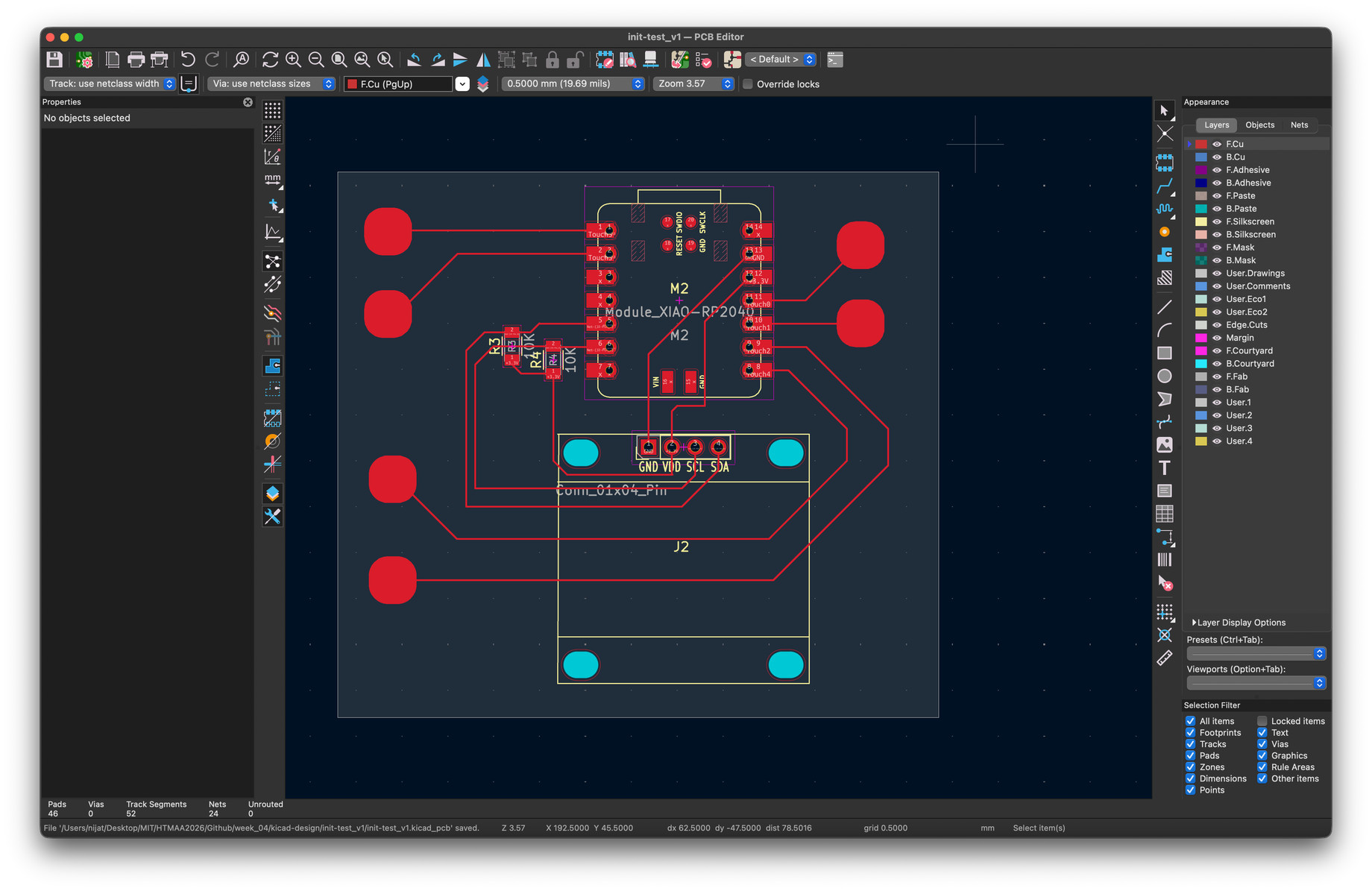
I placed the parts and routed the traces to the XIAO, the resistors, the display header and the six touch pads.
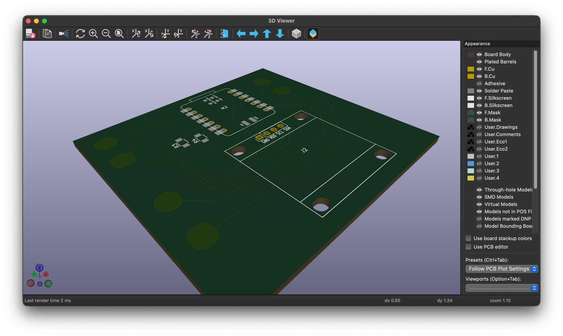
And the board in the 3D viewer.
Final board (initial)
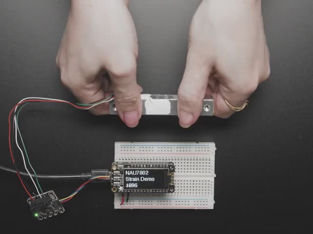
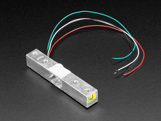
For the load, I'm looking at a 5 kg strain gauge load cell read through the NAU7802 24-bit ADC (images: Adafruit).
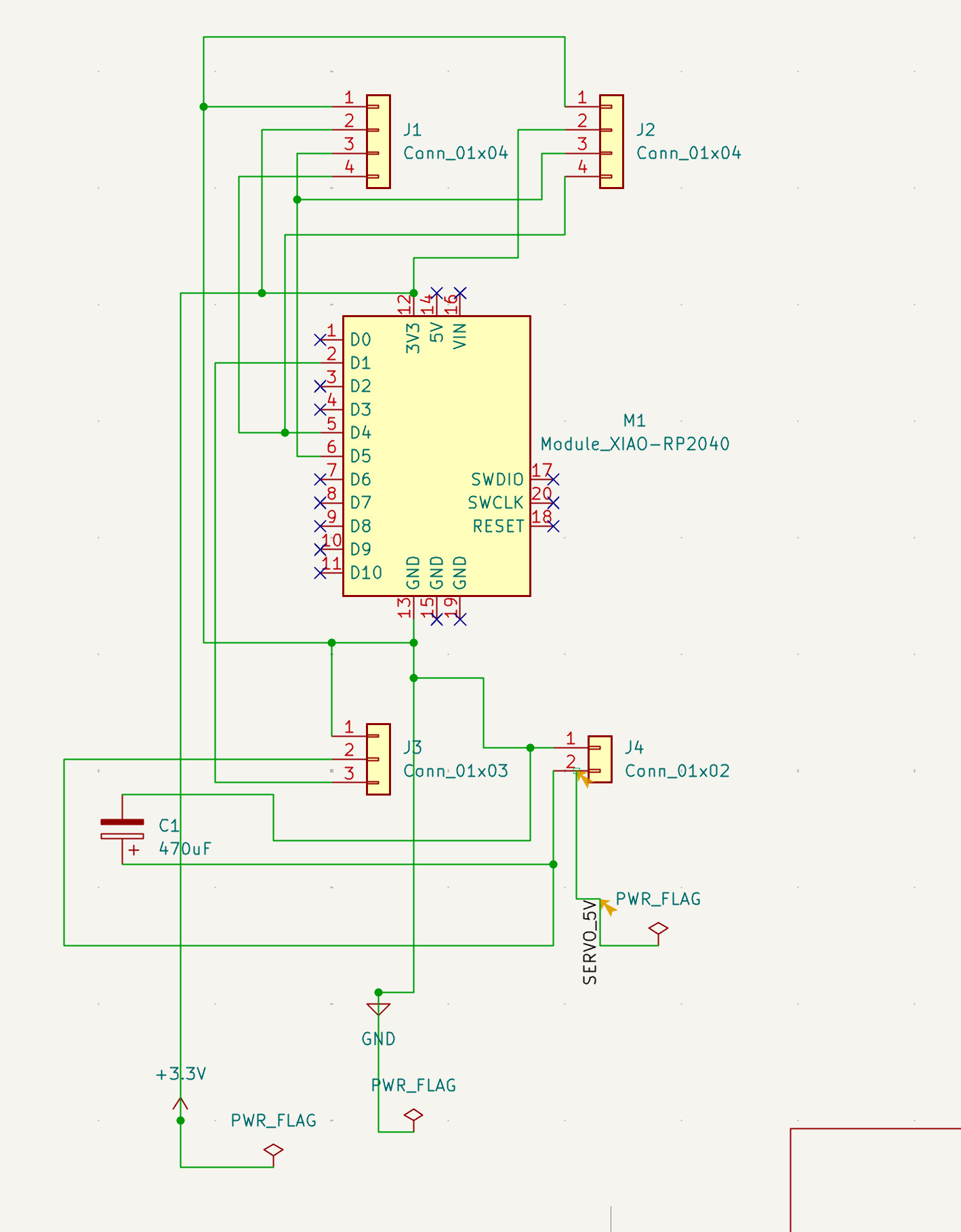
The initial schematic for the final board: XIAO RP2040, two 4-pin I2C headers, and a 3-pin servo header with its own 5V input and a 470 µF capacitor.
AI usage
Placeholder.